background image


Chapter 13  -  Optical Receiver 


10911 V01.06 

49


13.7.1 Operation


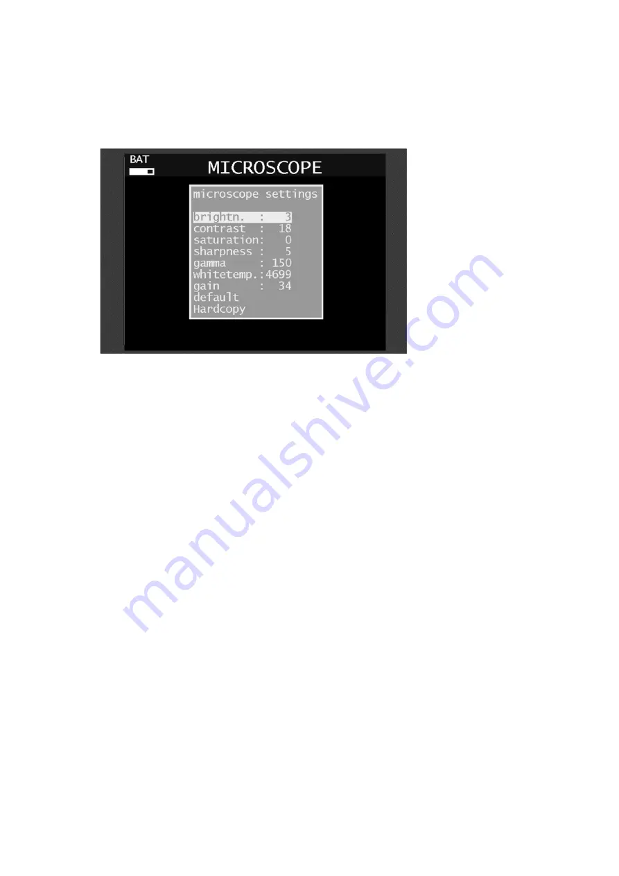
The microscope range is called up by pressing the 

MODE -> Microscope

 key. Select 

MODE

 to 

access the image settings menu. You can activate the individual menu items with 

ENTER

 and 

change the parameters by using the arrow buttons or entering the number directly.  


Selecting the 

Default

 menu item loads the microscope’s default settings. As the manufacturer's 

settings are not always ideal, you can permanently save the currently set values in the measuring 
instrument by selecting the 

SAVE

 button. You can load these values again any time by selecting the 

RECALL 

button. 

 
The 

ESC

 button allows you to exit the USB microscope section.   

13.7.2 Logging 

For documentation purposes, it is possible to make a hardcopy (screenshot) of the current 
microscope image. As the measuring instrument is only equipped with a USB interface, only 4 
images can be saved in the internal buffer of the measuring instrument. 
 
If all 4 memory locations are occupied, these images must be transferred to a USB stick. Then the 4 
memory locations are available again. 
 

Saving an image as a screenshot in the cache: 

 Open 

the 

MODE

->

Hardcopy 

menu item; if there is space available in the cache, the image 

will be saved. This can take several seconds; a corresponding message will appear on the 
screen 

“Screenshot saving…”

  The screen message changes to 

“Screenshot saved”

 as soon as the image is saved. 

  The message “no free memory loc.” appears if no more space is free in the buffer. All 

storage locations must first be saved to a USB stick. See the following point. 


Saving buffer images to a USB stick: 

  Exit the microscope section with the ESC button. 

  Unplug the USB microscope and connect a USB memory stick 

 Press 

MODE


  Select Memory -> 

Export Hardcopy -> USB


  Depending on the number of occupied storage locations, corresponding files are generated 

with the file name MICROSCOPE_xx.BMP, (xx represents a consecutive number). Files 
already saved on the USB memory stick are not overwritten. 

 
The message “Screenshots transferred, memory locations cleared” appears on the screen once the 
data has been successfully transferred to the USB memory stick. 

Содержание VAROS 109

Страница 1: ...2 4 4 Ventilation control 12 4 5 Switching on 13 4 6 Setting screen brightness and volume 13 CHAPTER 5 MENU STRUCTURE 14 CHAPTER 6 MEASURING RANGE 15 6 1 Frequency input 15 6 1 1 IF input 15 6 1 2 RF input 15 6 1 2 1 Ku band 15 6 1 2 2 C band 15 6 2 DVB S mode 16 6 2 1 Symbol rate input 16 6 2 2 Scan 16 6 2 3 DVB S parameters 16 6 2 4 BER measurement bit error rate measurement 17 6 2 5 MER measure...

Страница 2: ...PTER 9 MPEG DECODER 35 9 1 Program Service Information PSI 35 9 2 Network Information Table NIT 35 9 3 Picture and sound control 36 9 4 Display of MPEG video parameters 37 9 5 Video bit rate measurement 37 9 6 Dynamic program switching 37 CHAPTER 10 MEMORY MANAGEMENT 38 10 1 Saving 38 10 2 Recalling 38 10 3 Memory functions 38 10 3 1 Erasing the memory 38 10 3 2 Erasing a memory location 39 10 3 3...

Страница 3: ...52 15 2 Software version 52 15 3 Software update 52 15 4 Serial number 52 15 5 Default setting 52 15 6 Clock 52 15 7 Modulation 53 15 8 Botton tone beeper 53 15 9 Hardcopy 53 15 9 1 Transfer of the internally stored images to a USB stick 53 15 10 Activating software options 54 CHAPTER 16 DVI OUTPUT 55 CHAPTER 17 DATA LOGGER 56 17 1 Automatic recording of measurement sets 56 17 2 Transferring and e...

Страница 4: ...s Do not cover the ventilation slots on the instrument Covering the slots can result in reduced air circulation in the instrument which can cause heat build up and overheating of the electronic components Passage from the battery regulations BattV This device contains a battery which incorporates hazardous substances It must not be disposed of I domestic waste At the end of its working life it sho...

Страница 5: ...since they may damage plastic parts or the coating on the front panel Any dust should be removed from the ventilation slots regularly so that the air circulation provided by the built in ventilator is not obstructed 1 5 Calibration The instrument should be recalibrated at least every two years It is automatically calibrated at the factory in case of upgrading repairs or servicing 1 6 Service Servi...

Страница 6: ...rements LEVEL MEASUREMENT Measuring range 30 100 dBµV Information range 30 110 dBµV Resolution 0 5 dB Measuring accuracy Measuring range 2 0 dB at 20o C 2 5 dB 0o C 40o C Measuring bandwidth RB 10 MHz depending on symbol rate Acoustic level trend indicator can be switched on off Level trend bar with MaxHold Indicator ANALYZER digital analyzer Measuring bandwidth RB 10 MHz full span 4 MHz span 1 an...

Страница 7: ...ters Video bit rate measurement in Mbit s Video decoding MPEG 2 ISO IEC 13818 2 H 264 AVC Level 4 1 HP ISO IEC 14496 10 Audio decoding MPEG 2 ISO IEC 13818 3 Dolby Digital AC 3 Dolby Digital Plus MPEG 2 AAC ISO IEC 13818 7 MPEG 4 AAC ISO IEC 14496 3 CI Common Interface 1 CI slot Presentation of card menu Data logger Stores measurements automatically in the form of an XML file on a USB stick INTERF...

Страница 8: ...er supply 12V 2 5A included in delivery via extra low voltage jack according to DIN 45323 Power consumption max 30 W Storage battery Li Ion battery pack 7 2V 6 6Ah Operating time approx 3 5 hours dependant upon the LNB load automatic cutout as protection against exhaustive discharge Charging time approx 3 hours Battery management Battery can be charged using 12 V external supply ENVIRONMENTAL COND...

Страница 9: ... and connection elements pin configurations 10911 V01 06 9 Chapter 3 Control and connection elements pin configurations 3 1 Front Panel with Top and Bottom Section Top section of instrument Bottom section of instrument ...

Страница 10: ...Chapter 3 Control and connection elements pin configurations 10911 V01 06 10 3 2 Rear panel 3 3 USB A socket Pin 1 VCC 5 V Pin 2 Data D Pin 3 Data D Pin 4 GND ...

Страница 11: ...d connection elements pin configurations 10911 V01 06 11 3 4 DVI output Compliant with DDWG Digital Display Working Group DVI Digital Visual Interface Revision 1 0 3 5 12V power supply Extra low voltage jack per DIN 45 323 ...

Страница 12: ...ery is being charged the charge LED lights up red Once the battery is fully charged the internal battery management switches to maintenance charging and the charge LED turns green The instrument also has a charge status indicator A status bar in the frequency window indicates the remaining charge of the battery at all times If the battery charge becomes critical the word low appears in red next to...

Страница 13: ...s on the screen 4 6 Setting screen brightness and volume Pressing the AV SET button calls up two control bars one for screen brightness the other for volume Enter the desired settings using the arrow keys This function is not possible in some operating modes such as level measurement Pressing AV SET again or pressing ESC hides the bars and restores the original function of the arrow keys ...

Страница 14: ...currently set operating mode respectively This ensures that functions can only be selected where needed Selecting main menu Press MODE key Leaving the menu Press MODE or ESC key Selecting a menu point Select the desired menu item using the arrow keys Up or Down and press ENTER Back to previous menu level Press ESC key The picture shows the menu in the DVB S range with RF frequency input mode ...

Страница 15: ... GHz The frequency window displays SAT RF GHz This function serves to incorporate frequency conversion in an LNB from the transponder frequency RF to the first SAT IF depending on the LNB oscillator frequency LO For Ku band LNBs IF RF LO The instrument calculates RF IF LO For C band LNBs IF LO RF The instrument calculates RF LO IF 6 1 2 1 Ku band The device provides two user defined LNB oscillator...

Страница 16: ...uency input Pressing ENTER begins the process as indicated by the SCAN message in the frequency window When the instrument finds a transponder the scan is halted and the measuring receiver measures the frequency found Stop the scan by pressing a number key the Up or Down keys or the ESC key During the scan the instrument also detects DVB S and DVB S2 signals and switches the measuring receiver to ...

Страница 17: ...ated DVB S2 signals DVB S2 is a further development of DVB S In addition to QPSK a higher quality modulation scheme 8PSK has been introduced As an option pilots can be transmitted to help the receiver synchronise when reception conditions are not favourable Furthermore more efficient error protection LDPC BCH increases bandwidth effectiveness bit rate bandwidth at the same MER 6 3 1 Symbol rate in...

Страница 18: ...or rate and MER measurement is activated The measured values are shown in the BER window and the MER window The MPEG window is also displayed here you can follow the search for PSI program service information in the transport stream Further information can be found in the MPEG Decoder section 6 3 4 BER measurement bit error rate measurement As mentioned in the previous section the BER measurement ...

Страница 19: ...can be switched on or off at any time via the menu MODE Acoustic level on off 6 5 LNB supply The measuring receiver controls a connected LNB or a multiswitch using the conventional 14 18 V 22 kHz control max four SAT IF levels or with the DiSEqC control The supply is short circuit proof and provides a maximum current of 500 mA In the event of a short circuit or if the current is too high the instr...

Страница 20: ...ontrol Uncommitted switches which is operated via LNB Uncommitted Switch With Uncommitted switches you can split the 16 SAT IF levels that are possible with V1 0 into another 16 branches using the cascading option this is achieved using 4 additional switches uncommitted switches In total up to 256 SAT IF levels can be controlled The uncommitted switches are binary controlled The Up Down arrow keys...

Страница 21: ...y should show P42V Hi This setting connects the SAT IF route marked bold in the example All settings are incorporated in the tuning memory and can conveniently be recalled at a later date 6 5 2 3 DiSEqC V1 2 control Enter LNB DiSEqC V1 2 to open the DiSEqC V1 2 menu V1 2 can be used to control positioners with DiSEqC rotors The menu includes the selection of the 4 LNB levels identical to V1 0 and ...

Страница 22: ...ntrol LNB DiSEqC V2 0 activates the DiSEqC control V2 0 The difference from V1 0 is the additional feedback query of a controlled DiSEqC component When the device controls a multiswitch with DiSEqC V2 0 it sends an answer back to the device The instrument evaluates this feedback and reports DiSEqC reply correctly received if successful or DiSEqC reply incorrectly received if there is an error 6 5 ...

Страница 23: ...CABLE unit being used This figure shows the default settings with the following relationships SCR ADR0 1284 MHz SCR ADR1 1400 MHz SCR ADR2 1515 MHz SCR ADR3 1632 MHz SCR ADR4 1748 MHz SCR ADR5 1864 MHz SCR ADR6 1979 MHz SCR ADR7 2095 MHz Note Manufacturers have different methods for numbering the UBs They are numbered either from 0 to 7 or from 1 to 8 The physical address always goes from 0 to 7 F...

Страница 24: ... the cursor to the desired position in the label You can edit the label with alphanumeric characters using the arrows or the number keys The name can be up to 20 spaces in length Confirming and saving the entry Pressing the ENTER key closes the input menu and stores the values in the non volatile memory Wideband RF mode Some UNICABLE units LNB work exclusively on a single oscillator frequency This...

Страница 25: ... described above these UNICABLE units operate with a single oscillator frequency and the low and high bands combined on one band This reduces the number of SAT IF levels to 2 vertical and horizontal If the instrument is in this mode vertical V or horizontal H polarisation can be set via LNB SAT IF Layer This also switches the measuring receiver to RF frequency input mode A transponder frequency of...

Страница 26: ...u open 6 5 4 2 Operation The JESS control can be used to convert 16 SAT IF layers in a maximum of 16 UB slots These are further divided into 4 satellite positions with 4 SAT IF layers each Each connected receiver maximum of 16 operates using a dedicated UB slot This is defined via the UB number These JESS control parameters are set via LNB SAT IF Layer Satellite and UBs The measuring receiver is t...

Страница 27: ...SD6 series of wall outlets from Axing or the JAP series from Jultec etc Selecting LNB Prog ADo opens a Configurator which can be used to analyse and program an antenna wall outlet connected to the measuring instrument The figure below shows the measuring instrument in the antenna wall outlet configuration mode An X represents a locked user band UB bandpass slot and a green check mark indicates an ...

Страница 28: ...s now in line n 2 etc If the programming was not successful the message DiSEqC answer incorrect appears briefly and the lines n 1 to n 3 remain unchanged the configuration is transmitted using DiSEqC commands Note The search function in the operating mode of JESS has been deactivated 6 5 6 LNB current measurement The measuring receiver measures the power of the direct current that comes from the R...

Страница 29: ...pectrum SPAN1 above and below the measuring frequency When the UNICABLE control is active the analyzer displays the frequency spectrum above and below the centre frequency of the last UB slot that was activated 7 2 Frequency segment SPAN The frequency segment SPAN can be changed In FULLSPAN mode the frequency segment spans the entire measuring range The frequency segment SPAN can be changed using ...

Страница 30: ...ess ENTER to begin the process When the UNICABLE control is active the frequency display always refers to the spectrum that was converted by the UNICABLE unit If the ANALYZ button is then pressed again the instrument returns to analyzer mode 7 6 1 Switching to measuring receiver mode with SCAN A menu will appear as soon as the scan button is pressed here you can choose between SAT SCAN and TRANSPO...

Страница 31: ...r position In addition to the five preset symbol rates the entire range of the symbol rates is searched from 2 to 45 MSym s 7 7 Activating the remote supply The LNB supply can be activated while in analyzer mode in the same way as was discussed in previous sections First press the LNB button to access the relevant menu ...

Страница 32: ... the chapter ANALYZER changing over into the measurement mode is described in SCAN 8 1 SAT SCAN This function can be choosen from the above displayed menu with the keys SCAN or ENTER A search cycle starts in a range from east to west where the most important satellites are tuned to the transponder The positions that are being tested will be shown in a distinct red window and a reference searching ...

Страница 33: ...pen the SAT list by pressing SCAN in the main menu Use the and arrow keys to browse through the list page by page individual satellites can be selected using the Up and Down keys Pressing the SCAN button again displays the transponder list for the selected satellite The SAT list is provided by the instrument manufacturer and updated on a regular basis Check whether the list being used is up to dat...

Страница 34: ...appear at the top of the SAT list and are marked with You can replace one favourite with another at any time With MODE Satlist Erasing Favourites list to erase all favourites 8 5 Importing a SAT list Open the Satlist menu from the main menu press MODE The following submenu is then displayed The current SAT list can be found at www kws electronic de To import a SAT list you first need to connect a ...

Страница 35: ...interpret these PSI tables in order to give the user an overview in the form of channel lists This process can take a few seconds depending on the number of programs they contain and can be monitored in the MPEG window The MPEG window is seen at the bottom left of the screen While this is being displayed a new channel search is running in a DVB S transponder For a quick overview of the current tra...

Страница 36: ... select the corresponding entry from the NIT As described in section Memory management saving you can then select a memory location and save the NIT entry SAVE takes you to the SAVE menu If the NIT has more than 10 entries the and keys can be used to scroll between the pages of the list 9 3 Picture and sound control As explained in section Program Service Information PSI several video and audio ch...

Страница 37: ...G video parameters As soon as a live picture can be seen the MPEG decoder displays the following parameters in a window at the lower right edge of the screen Profile and level e g MP ML Chroma format e g 4 2 0 Video resolution e g 720 576 Letter Box Format 4 3 or 16 9 The parameter window can be displayed or hidden at any time using the or arrow keys 9 5 Video bit rate measurement The MPEG decoder...

Страница 38: ... instrument issues a warning To overwrite the memory press the ENTER or SAVE button a second time 10 2 Recalling Press the RECALL button to open the Recall menu When this menu is opened for the first time after the instrument is switched on the instrument suggests memory location 1 Each time the recall function is accessed the memory location number increases by one That means that the instrument ...

Страница 39: ...ction This function can be used to protect the entire tuning memory groups of memory locations or individual memory locations This prevents a memory location from being overwritten by mistake Access via MODE Memory Protection memory Similar to the description in section Erasing a memory location the instrument asks for the first and last memory location to be protected Press ENTER to start the pro...

Страница 40: ...f the instrument with the data from the mem file The name of the selected mem file is saved in the instrument as a system name and displayed in the header of the Save menu This name is suggested as a file name during the next measurement Note Any other general settings by the user such as LNB oscillator frequencies for RF inputs or the UB centre frequency for UNICABLE or JESS are not transferred w...

Страница 41: ...on in high speed mode The measuring instrument only supports the MASS STORAGE DEVICE class USB stick The measuring receiver software can read files from and write files to a USB stick using the FAT32 file system A USB stick is used to carry out firmware updates or to record measurement data DataLogger We recommend using the original USB stick from the instrument manufacturer The USB stick is inclu...

Страница 42: ...nt When inserting the module ensure that the polarity is correct and that the barcode is pointing down Do not force the module into the slot if there is significant resistance The version firmware can be activated in the instrument by MODE Settings Software Info 12 2 Operation The inserted module is initialised when the instrument is cold started Use the Common Interface menu to query the inserted...

Страница 43: ...Chapter 12 Common Interface 10911 V01 06 43 ...

Страница 44: ... snap plug connection An SC APC plug connection is built into the measuring instrument The measuring instrument is equipped with an optical receiver that converts the light signal back into an RF signal After the optical receiver the RF signal behaves as if it had been supplied via the coax input of the measuring receiver This means that all the measurements available through the RF input can also...

Страница 45: ... set the wavelength used because it is required for measurement of the optical power and the optical modulation index OMI The responsivity of the integrated photodiode depends on the wavelength Using MODE Settings Wavelength LAMBDA second page you can set the wavelength as 1310 nm 1490 nm or 1550 nm 13 4 Measuring the optical power Optical transmission involves modulation of the intensity of the l...

Страница 46: ...f the optical modulation index is doubled e g increased from 2 to 4 with the same optical power the RF voltage after the optical receiver increases by 6dB This means that the OMI and RF voltage are linearly proportional to one another 13 6 Remote supply An optical LNB can be supplied with a voltage of 14 V and max 500 mA using the F connector For Invarcom FibreMDU and equivalent products you can u...

Страница 47: ...h can be disrupted in the core region good physical contact can be prevented in the plug connector cause scratches and associated damage The following figure shows a typical example of a poor physical contact in a plug connector Here a dust particle prevents the two optical fibres from creating a flush contact with one another ...

Страница 48: ... magnification of 200 The core of the optical fibre is visible in the centre Typical requirements for single mode fibres Zone name diameter Scratches Damage A Core 0 9µm 0 25µm Non permitted Non permitted B Cladding 25 120µm No limits all 2µm 5 in 2 5µm range None 5µm C Adhesive 120 130µm No limits No limits D Contact 130µm No limits No limits The figure shows the schematic structure of a typical ...

Страница 49: ...locations are occupied these images must be transferred to a USB stick Then the 4 memory locations are available again Saving an image as a screenshot in the cache Open the MODE Hardcopy menu item if there is space available in the cache the image will be saved This can take several seconds a corresponding message will appear on the screen Screenshot saving The screen message changes to Screenshot...

Страница 50: ...possible for you to draw conclusions about the type of signal interference based on the form of the constellation diagram This is explained later using examples The mean between two ideal states is designated as the decision limit indicated in the diagram by horizontal and vertical lines A signal with enough interference to move several signal states beyond the decision limit will result in bit er...

Страница 51: ...Chapter 14 Constellation diagram 10911 V01 06 51 Ideal constellation diagram signal source SFU Rohde Schwarz 8PSK signal with 8 I Offset signal source SFU Rohde Schwarz ...

Страница 52: ... into the instrument and select MODE Settings Software Update A selection appears containing all saved bin files Select the desired file using the arrow keys Up Down and press ENTER to start the software update The instrument deletes the old version from the memory before writing the new software to the internal flash drive This takes approximately 1 minute Note You can find the latest information...

Страница 53: ...poses the contents of the screen can be saved on a USB stick or alternatively one of 2 two internal memory locations provided the instrument is in tuned mode or analyzer mode Videos and drop down menus for settings etc cannot be copied By selecting MODE Hardcopy you can access a menu where you can choose between Hardcopy USB Hardcopy int memory location and USB Directory Any existing files with th...

Страница 54: ...a message on the screen Screenshots transferred memory locations cleared 15 10 Activating software options Software options can be activated by entering an 8 digit key code You can request the individual key code for each option from the manufacturer MODE Settings SoftwareKeys takes you to a submenu which currently only offers the constellation diagram option To activate this option confirm the me...

Страница 55: ...e DVI output before the instrument is switched over When the instrument is switched off and restarted the picture is shown again on the internal display DVI stands for Digital Visual Interface HDMI means High Definition Multimedia Interface Physically the interface is designed as a DVI I socket However the protocol is HDMI compliant This means that both video and audio data are transmitted The mea...

Страница 56: ... ESC or press ENTER to overwrite the existing file Then enter the individual measurement parameters The instrument now refers to the tuning memory whereby only the first and last memory locations need to be entered for the measurements Any unassigned memory locations are skipped The instrument then automatically accesses the tuning memory locations one by one and saves the measured values in the x...

Страница 57: ...below shows a set of measurements in MSExcel 17 3 Deleting measurement sets from the device If the USB stick is in the instrument you can enter MODE DataLogger Directory to access the files saved on the external memory The remaining memory capacity of the USB stick can also be seen in percent For example the file shown above takes up 18 KB on a USB stick With a capacity of 512 MB approx 29 000 mea...

Страница 58: ...15 Calibration 5 Card menu 42 Cleaning 5 Cleaning the fibre optic plug connection 46 Clock 52 Common Interface 42 Constellation diagram Option 50 Contents 1 Control and connection elements pin configurations 9 Cursor 29 D DATA LOGGER 56 Default setting 52 Deleting measurement sets from the device 57 Disable memory protection 39 DiSEqC 19 DiSEqC V1 0 control 20 DiSEqC V1 1 control 20 DiSEqC V1 2 co...

Страница 59: ... 28 LNB supply 19 Logging 49 M Mains operation 12 Maintenance 4 Management of the instrument 52 MAX Hold function 19 Measuring range 15 Measuring the optical modulation index OMI 46 Measuring the optical power 45 Memory export 39 Memory functions 38 Memory import 39 Memory management 38 Memory protection 39 Menu structure 14 MER measurement 17 18 Modulation 53 MPEG decoder 35 N Network Information...

Страница 60: ...5 Setting screen brightness and volume 13 Setting the wavelength 45 Software update 52 Software version 52 Sorting the memory 39 Specifications 6 Startup 12 Switching on 13 Switching to measuring receiver mode 30 Switching to measuring receiver mode with SCAN 30 Symbol rate input 16 17 T Transfer of the internally stored images to a USB stick 53 Transferring and evaluating the measurements on a PC...

Отзывы: