Kval Acro-HD Скачать руководство пользователя страница 56

Troubleshooting with the Status Light Panel

4-8

KVAL Acro-HD Operation/Service Manual

1. 

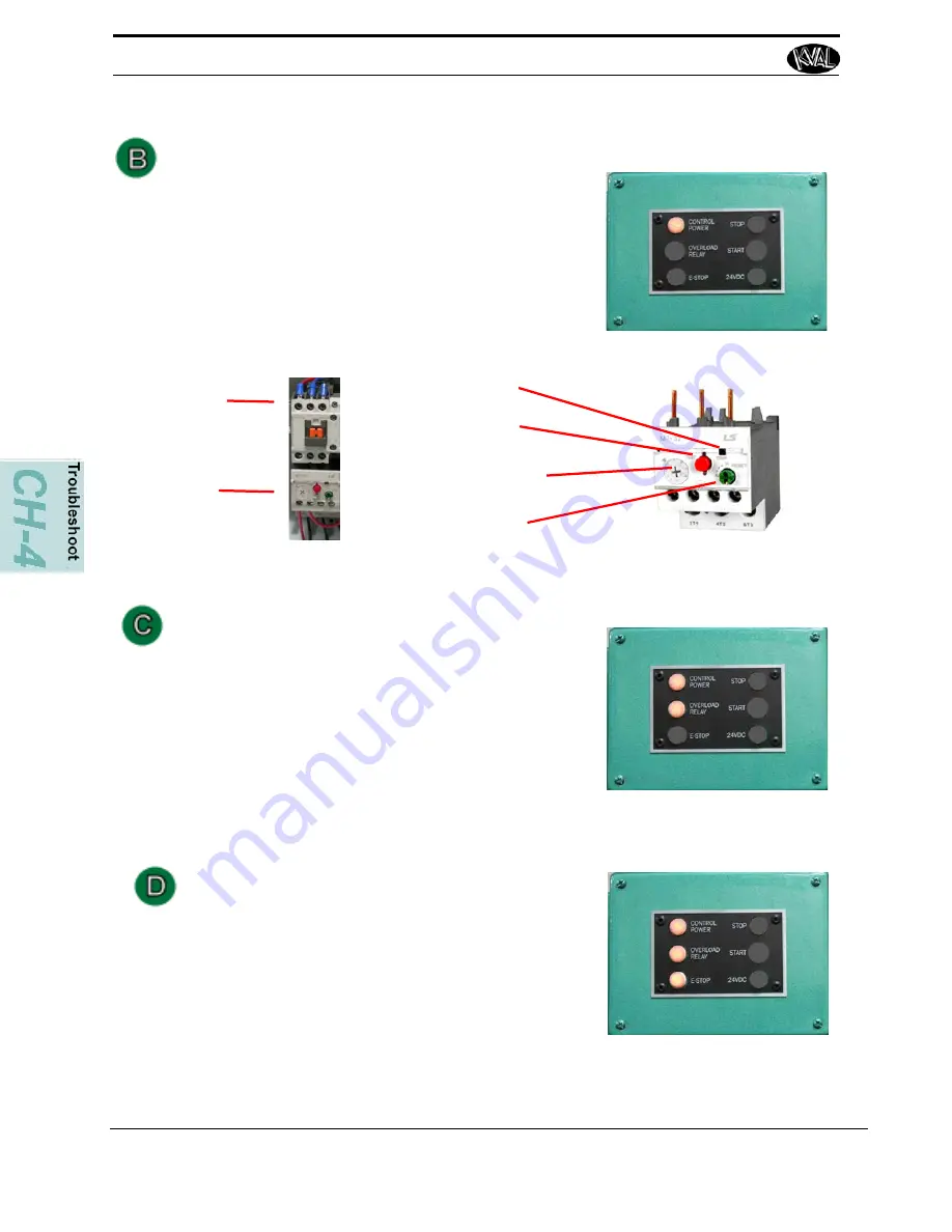
Check Motor Overload Circuits

2. 

With power on, check the trip indicator LED on the 

overload. If indicator is orange, press the Reset 
Button to reset the overload circuit. Retest the 
Machine.

Overload Relay Light OFF

Contactors

Overload 

Relays

Reset Button. Fac-
tory set on the ''H'' 

Setting.

Test or Stop

Trip Indicator

Factory Set Current 

Rating Adjust

E-Stop Light OFF 

Check if any E-Stop buttons are pulled out.


NOTE: 

Location and quantity of E-Stop buttons varies 

depending on customer need. Typical locations for E-
Stop buttons are near the Rear Access Gate and near 
the Tool Changer Access Gate

Stop Light OFF

Check for 120 VAC between #2 and #4 If there is 
voltage, press the Start button. If no voltage, check 
the Stop button to make sure it is all the way out and 
not stuck in, then check the contact to make sure it is 
closed. If still no voltage, check the wiring.

Содержание Acro-HD

Страница 1: ...Innovation Quality Honesty Operation and Service Manual Published 2 18 20 Acro HD Entry Door Center Acro HD Operation and Service Manual ...

Страница 2: ...ks or registered trademarks of their respective holders all rights reserved Reference to these products is not intended to imply affiliation with or sponsorship of Kval Incorporated Contacting KVAL Customer Service For further information about this manual or other Kval Incorpo rated products contact the Customer Support Department Mailing address Customer Support Department Kval Incorporated 825 ...

Страница 3: ...r user experience with our product that is the manual the machinery the software etc What was easy or difficult to use or to learn If you could change something about the design what would it be Please email your comments and suggestions for improve ment to userexperience kvalinc com NOTE This is not a customer support email link For that please refer to the Customer Service contact information ab...

Страница 4: ...KVAL Acro HD Operation Service Manual ...

Страница 5: ...e Steps Before Lockout Tagout 1 8 Lockout Tagout Power 1 8 Lockout Tagout Air Supply 1 9 Start Maintenance 1 9 Post Maintenance Steps 1 9 Zero Energy to Start Up 1 10 Getting Help from KVAL 1 12 On Line Help 1 13 Product Return Procedure 1 13 Safety Sign Off Sheet 1 15 A Note to the Operator 1 15 Chapter 2 Operation of the Acro HD Operator s Tour 2 2 About the Side Machine Controls 2 4 About The F...

Страница 6: ...brication Requirements 3 3 Pillow Block Bearing Housings 3 3 Flange Bearing Housings 3 4 Ball Rail Bearing 3 4 Grease Points 3 5 Description of Air Input System 3 6 Air Input with Lubrication 3 6 Air Line Without Lubricator 3 7 Chapter 4 Troubleshooting the Acro HD About Sensors 4 2 Adjusting Limit Switches 4 3 Troubleshooting the Air Cylinders 4 4 Adjusting Cylinder Extension Speed 4 5 Adjusting ...

Страница 7: ...About this Manual 1 2 Safety First 1 3 Safety Sheet Sign Off Sheet 1 3 Safety Terminology of Labels 1 3 Safety Guidelines 1 3 Lockout Tagout Procedure 1 7 Follow the P R O P E R lockout rule of thumb 1 9 Zero Energy to Start Up 1 10 Zero Energy State to Start Up to Operating State 1 10 Getting Help from KVAL 1 12 On Line Help 1 12 Product Return Procedure 1 12 Safety Sign Off Sheet 1 15 A Note to ...

Страница 8: ...Maximum light width is 28 1 2 Adjustment for either in swing or out swing door units is also completely automatic Manual adjustment of the door support arms is necessary for door lights wider than 25 or for 3 6 doors This operation takes less the 60 seconds and no tools are required DOOR SIZE SPECIFICATIONS Door height 6 8 7 0 or 8 0 Door width 2 6 to 3 6 Door thickness 1 3 4 Option s Option A Doo...

Страница 9: ...damaged or illegible There are three types of warning labels or decals DANGER means if the danger is not avoided it will cause death or serious injury WARNING means if the warning is not heeded it can cause death or serious injury CAUTION means if the precaution is not taken it may cause minor or moderate injury Safety Guidelines In addition to the caution and warning labels affixed to this machin...

Страница 10: ...t down Never perform any maintenance unless machine is at zero state Never clean the machine while it is running Never walk away from the machine while it is running When the Machine is ON The compressed air system connected to this machine should have a three way air valve for shut off and pressure relief All cylinders on machine are under high pressure and can be very dangerous when activated Be...

Страница 11: ...located at different locations Before performing any repairs or mainte nance lockout and tagout must be installed at all locations All maintenance and repairs to electrical circuitry should only be per formed by a qualified electrician Still has power in OFF position Electrical Prior to performing any maintenance repairs cleaning or when clearing jammed debris you must disconnect tag out or lock o...

Страница 12: ...ident If you believe any part or operation of this machine is in violation of any health or safety regulation STOP pro duction It is your responsibility to immediately protect your employees against any such hazard Additional detailed safety guidelines are included in the operating instructions of this manual KVAL will be pleased to review with you any questions you may have regarding the safe ope...

Страница 13: ...ock and tag on each disconnect Only each operator may remove their own lock and tag Important When many people are all working on the same machine you will need a multiple lockout device such as the one shown here Follow the P R O P E R lockout rule of thumb P Process shutdown R Recognize energy type electrical pneumatic mechanical etc O OFF Shut off all power sources and isolating devices P Place...

Страница 14: ... air supply and pressure spring tension weight shifts etc 2 Inform all affected personnel of the eminent shutdown and the duration of the shutdown 3 Obtain locks keys and tags from your employer s lockout center 4 Turn off machine See Chapter 2 for power down and power up procedures 5 Turn the disconnect switches on ALL electrical and frequency panels to the OFF position Then push the red tab to p...

Страница 15: ...etc are completely removed and that all guards and safety devices are installed 10 Before removing the locks and tags the person who attached them shall inspect the equipment to ensure that the machine will not be put in an unsafe condition when re energized 11 The lock and tag can now be removed only by the person s who placed them and the machine can be re energized 12 The tags must be destroyed...

Страница 16: ...cally when energy is restored Remove Locks Each operator must remove his or her own lock and tag This will ensure that all oper ators are in a safe place when the equipment is started Perform Visual Checks If the equipment is too large to see all around it station personnel around the area and sound the personnel alarm before starting the equipment If your operation is more complex your company s ...

Страница 17: ... the key to your lock Proper lockout tagout can save lives limbs and money Help make your work environment safe for you and your fellow workers Be sure to follow the P R O P E R lockout tagout procedures and that those around you do also Close the Cage Gate Verify all cage gates are securely closed Ensure all safety protocols are in effect ...

Страница 18: ...nd record the serial number 3 phase volts electrical print number and air print number 2 Contact our customer support team In the U S and Canada call 800 553 5825 or fax 707 762 0485 Outside the U S and Canada call 707 762 7367 or fax 707 762 0485 Email address is service kvalinc com Hours 6 00 AM to 4 00 PM Pacific Standard Time Monday through Thursday 6 30 AM to 1 30 PM Pacific Standard Time Fri...

Страница 19: ...nswers to the following questions What is the extent of the failure reason for return What are the relevant error mes sages or error codes How long did it operate Did any other items fail at the same time What was happening when the unit failed e g installing the unit cycling power starting other equipment etc How was the product configured in detail Which if any cables were modified and how With ...

Страница 20: ...Getting Help from KVAL 1 14 KVAL Acro HD Operation Service Manual Page Intentionally Left Blank ...

Страница 21: ... follow my company s safety procedures I have read and understand these guidelines Machine Safety Concerns I have been given a tour of the machine and understand all the safety labels E Stops and the actions to take in case of an emergency I will make sure all guards are in place before operation I will turn off the compressed air before loading hardware staples screws etc I will turn off the elec...

Страница 22: ...Safety Sign Off Sheet 1 16 KVAL Acro HD Operation Service Manual ...

Страница 23: ...cro HD Chapter 2 at a Glance Operator s Tour 2 2 About the Side Machine Controls 2 4 About The Foot Pedals 2 4 About the Door Insert Pedals 2 5 About the Door Pivot Pedals 2 5 About Acrobat Control 2 6 About Door Alignment Pads 2 7 About Sensors 2 8 About the Electrical Panels 2 8 Description of the Six Light Panel 2 9 Run the Acro HD 2 11 Running a Door Only 2 11 Using the Acrobat 2 13 Using the ...

Страница 24: ... Door Light Insert Table Transparent for Illustration purposes Hydraulic Pump for Door Lift Air Valve Movable Door Clamp for Pivot Fixed Door Clamp for Pivot 8 0 Piston for Door Clamp 6 8 7 0 and 8 0 Pis ton and Door Clamp Tilt Acrobat Off Load Sensors I 0006 I 0010 I 0004 Limit Switches for Tilt Acrobat I 0032 I 0033 Sensors I 0007 I 0005 Door Frame Alignment Pads Hinge Support Jambs Door Frame A...

Страница 25: ...side views of the Acro HD FIGURE 2 2 Side Views Acrobat Hydraulic Lift Electrical Panel Acrobat Piston Out Swing Door Pistons Located on Both Sides of Machine Foot Pedal Controls Door Insert X2 Door Pivot X2 Acrobat Up and Down Side Controls Located on Both Sides of Machine Out Swing Control Out Swing Control ...

Страница 26: ...ls are used as part of the setup such as select door length override the down limit and emer gency stop FIGURE 2 3 Side Controls About The Foot Pedals The foot pedals are main controls to process the door The foot pedal types are as follows Door Insert Pedals X2 Door Pivot Pedals X2 Acrobat Up and Down Optional Choose Door Size Emergency Stop Down Limit Override Used with Out Swing Doors ...

Страница 27: ...t table can be raised and lowered in small increments to allow full con trol of the light into and away form the cut out by pressing the foot pedal in short taps rather than fully depressing the pedal The Door Insert Pedals work in sequence Below is the order of sequence for the Up and Down pedals Door Insert Table Up Foot pedal order of operation is Step 1 Raises the table from a fixed posi tion ...

Страница 28: ...ce for the Up and Down pedals Door Pivot Up Foot pedal order of operation is Step 1 Raises the door pivot into position Step 2 Clamps the door under low pressure Step 3 Clamps the door under high pressure and then raises the door Now the door can be flipped for an opposite hand door Door Pivot Down Foot pedal order of operation is Step 1 Lowers the door from the fully raised position Step 2 Unclam...

Страница 29: ...ed by a black button located the side of the machine Each lift is independently controlled Pull out the button to lift push the button in to lower Up Pedal The Up Pedal tilts the out feed end of the machine to allow easy handling of the com pleted door frame Down Pedal The Down Pedal returns the lift to a position to roll on the door Down Pedal Up Pedal Out Swing Control X2 ...

Страница 30: ...rvice Manual About Sensors There are sensors located on the Clamp Hydraulic Assembly at the lowest and highest points of the piston range See Figure 2 1 on page 2 2 for sensor locations FIGURE 2 4 Sensor Location Movable Clamp Sensor Sensor Sensor ...

Страница 31: ...le Logic Controller Contains tilt motor and table motor overload relay circuits Contains the foot pedal terminals Contains fuses Contains a 24VDC Warning High Voltage is present in this panel at the top of the Three Phase Input even with the disconnect off If working on the panel follow safety pro tocol as described in Chapter 1 Main Electrical Panel ACR PLC 24VDC Power Supply 120Vac and 24VDC Ter...

Страница 32: ...erload Relay 3 E Stop 4 Stop 5 Start 6 24VDC Control Power light illuminates when the Control Transformer is pulled out and the power is working on secondary side of transformer Overload Relay The overload circuit is working when light is on E Stop The back gate is closed and Frame E stop is not acti vated when this light is on 24VDC light comes on once the ACR is latch and the 24VDC power Supply ...

Страница 33: ...e Acro HD See How to Power Up the Acro HD on page 2 16 3 Select door size from the side control panel 8 0 7 0 or 6 8 4 Place light on Door Light Insert table 5 Roll door over the table centering over the light 6 Raise the door pivot to the clamping stage This will secure the door so you can move the light into position without the door moving If the opposite hand is required raise the door up and ...

Страница 34: ...and hold the Door Insert Up pedal a second time to raise the light into the cut out Note For greater control tap the foot pedal to raise the light in small increments until the light is aligned with in the cut out 10 Fasten the light with in the opening Note If attaching a frame to the door go to Using the Frame Alignment Lifts on page 2 13 if not continue with next step 11 Press and hold the Door...

Страница 35: ...he door and flip it to the opposite side 17 To bring the door down to the rollers press and hold or tap the Door Pivot Down pedal 18 Complete the assembly 19 To unclamp the door press and hold or tap the Door Pivot Down pedal a second time 20 Press and hold or tap the Door Pivot Down pedal a third time to move the clamps out of position Use the Acrobat to remove the door from machine 1 During the ...

Страница 36: ...Override button while simultaneously pressing the Down Pivot switch foot pedal b Attach the sill to the bottom of the door Press Together 7 Attach Brick Moulding 8 Roll out door to Acrobat and follow the instructions in Using the Acrobat Option on page 2 15 Note If building a Out Swing Door engage the Out Swing Pivot Wheels See Figure 2 1 on page 2 2 for location of wheels ...

Страница 37: ...flush against the door shelf 2 To move the table to the unload position press and hold the Acrobat Tilt Up pedal The door will move up for easy removal 3 To reset the table press and hold the Acrobat Tilt Down pedal 4 If continuing door process repeat steps 3 through 23 5 If powering down the machine See How to Power Down the Acro HD on page 2 17 Acrobat Tilt ...

Страница 38: ...re system How to Power Up the Acro HD 1 Ensure factory air is applied to machine and main air supply is turned on 2 Check that all E Stop buttons are out 3 Make sure the electrical disconnect the electrical cabinet is turned to the ON position 4 Pull the CONTROL TRANSFORMER switch out to the On position It should light up 5 Push the green START MACHINE button 6 All lights on the status light panel...

Страница 39: ...tri cal storms Emergency Shutdown and Recovery There are emergency shutdown E Stop switches located at both sides of the machine The E Stop switches are to be used when the machine is out of control or is about to damage personnel or equipment When an E Stop switch is activated power to the machine is killed The machine responds in the same way if you press the STOP button on the operator s statio...

Страница 40: ...Powering Up and Powering Down the Acro HD 2 18 KVAL Acro HD Operation Service Manual ...

Страница 41: ...your KVAL machine maintained is an important piece for successful operation of your door production pro cess Chapter 3 at a Glance Lubrication Schedule 3 2 Typical Lucubration Kit 3 2 Lubrication Requirements 3 3 Pillow Block Bearing Housings 3 3 Flange Bearing Housings 3 4 Ball Rail Bearing 3 4 Grease Points 3 5 Description of Air Input System 3 6 Air Input with Lubrication 3 6 Air Line Without L...

Страница 42: ... Flange Block Bearing Ball Screw Every 80 Hours of Machine Operation Tapered Bearing One Pump 4 X a Year Air Line Lubricator One drop of oil every 2 or 3 cycles Check the lines every week to two weeks Note Some CNC Machines drop every 5 10 cycles Either lubricant listed below is approved to use KVAL P N SYSLUBG Chevron AW Hydraulic Oil 32 G C lubricants light AW R O Mobile DTE 24 Shell Tellus32 Gu...

Страница 43: ... The Zerk fitting is basically a valve that opens under pressure to allow lubricant to pass through a channel and be forced into the voids of the bearing When the pressure stops the ball returns to its closed position The ball excludes dirt and functions as a check valve to prevent grease escaping back out of the fitting The ball is almost flush with the surface of the fitting so that it can be wi...

Страница 44: ...for reliable operation FIGURE 3 6 Flange Bearings Ball Rail Bearing Ball Rail Bearings are linear bearings that are attached to positioning rails In most cases the bear ings are attached to assemblies to move them in the X Y or Z direction FIGURE 3 7 Ball Rail Bearings Greasing Flange Bearing Bearing Housings Approximatively 1 Gram one pump from grease gun of Dura Lith Grease KVAL P N Lube EP 2 Ev...

Страница 45: ...ttings and apply EP 2 grease Use an extender to reach tight areas Make sure to Lockout Tagout before maintenance For recommended greasing schedule see Lubrication Schedule on page 3 2 To get access to the bearings the Hinge Covers will have to be removed Rail Bearings X10 Hub Bearings X8 ...

Страница 46: ...s delivers the lubricated air to valve banks and air cylinders FIGURE 3 8 Typical Air Line Filter and Lubrication System Adjusting the Air Line Lubricator Using the knob on the top of the lubricator adjust until one drop per every other cycle is used as observed through sight glass Shop Air Input Air On Off Knob Muffler Filter purge Pressure Gauge with adjust Clean Dry Air CDA to Air Blow Off Lubr...

Страница 47: ...lf Harmony 32 To prime the lubricator find an air line on the carriage section of the machine that is energized and disconnect it allowing the air stream to bleed air pressure away from any persons Direct the air stream at the machine so you can see when there is an oily film blowing out of the air hose Repeat this same procedure for the back section and other trouble areas It is recommended to ch...

Страница 48: ...Description of Air Input System 3 8 KVAL Acro HD Operation Service Manual ...

Страница 49: ...imit Switches 4 3 Troubleshooting the Air Cylinders 4 4 Adjusting Cylinder Extension Speed 4 5 Adjusting Cylinder Retraction Speed 4 5 Troubleshooting Electrical Problems 4 6 If the Power Stops During Normal Operation 4 6 Refer to the Air and Electrical drawings provided with delivery of the machine The drawings are normally located in the Electrical Panel If copies are unavailable contact the KVA...

Страница 50: ...scillator create a field generating out the front of the sensor When a metal object enters the field a loss in amplitude occurs The detector circuit recognizes the loss of ampli tude and generates 0VDC to send to the PLC When the metal object leaves the sens ing area the sensor to returns to 24VDC and sends it to the PLC As a result if a metal object is sensed the output of the sensor equals 0VDC ...

Страница 51: ...d cycle check the limit switches A worn limit switch arm or a mis adjusted limit switch is more than likely the cause Depending on the model of limit switch on your machine the pre travel amount of movement from the limit switch arm s resting position to the position at which the switch actuates with a click is either 5 or 20 degrees The Acro HD has three 5 degree switches If the arm is moved to t...

Страница 52: ...port this regulates the air flow exhausting from the cyl inder and the opposite is true for the retract motion 1 Check the air pressure to the machine 2 Check the flow controls to see that they are adjusted correctly and to the proper specifications 3 Check for any obstructions to the cylinders such as screws or a misplaced tool etc FOLLOW ALL SAFETY GUIDELINES AND SIGNS DURING THIS PROCESS 4 Chec...

Страница 53: ...a new cylinder c If the valve is not receiving an electrical signal for instructions It might be necessary to call in a specialist or check with KVAL customer service at 1 800 553 5825 5 If an Air Leak is coming from an exhaust port on the solenoid air bank a Check the solenoid for the manual override If the solenoid has a manual over ride you can push each of the buttons one at a time When the ai...

Страница 54: ... the cause NOTE Be sure to proceed down the table starting with the CONTROL POWER light STEP 1 Control Power Amber If light is OFF go to item A on page 4 24 STEP 2 Overload Relay Amber If light is OFF go to item B on page 4 25 STEP 3 E Stop Amber If light is OFF go to item C on page 4 25 STEP 4 Stop Amber If light is OFF go to item D on page 4 25 STEP 5 Start Amber If light is OFF go to item E on ...

Страница 55: ...eck the wiring of the black and white wire going from the Control Transformer to the 120 VAC Terminal Strip 7 If there is no power between 1 and 2 check the secondary side of the trans former a Check between X1 and X2 If no power is measured it is a bad transformer b If there is power at X1 and X2 check the other side of the fuse If now power replace the fuse 2 Is the Disconnect Switch on the main...

Страница 56: ...Test or Stop Trip Indicator Factory Set Current Rating Adjust E Stop Light OFF Check if any E Stop buttons are pulled out NOTE Location and quantity of E Stop buttons varies depending on customer need Typical locations for E Stop buttons are near the Rear Access Gate and near the Tool Changer Access Gate Stop Light OFF Check for 120 VAC between 2 and 4 If there is voltage press the Start button If...

Страница 57: ...heck for DC voltage where those wires were disconnected If no voltage Check the input side for 120 VAC If no 120 VAC check the fuse If there is 120 VAC and no 24VDC replace the 24VDC Power Supply If there is 24VDC Reconnect the V wire to the 24VDC power supply Trace the output wire to the DC terminal block Disconnect all 24V positive wires from the DC from the DC terminal block except the output w...

Страница 58: ...Troubleshooting with the Status Light Panel 4 10 KVAL Acro HD Operation Service Manual ...

Страница 59: ...mit switches 5 degree description4 3 adjustment4 3 location on EP 14 3 linear bearing maintenance schedule3 2 lockout and tagout Guidelines1 10 lockout procedure1 8 M main electrical panel description2 9 O overload relay light description2 10 P pillow block bearing maintenance schedule3 2 PLC location in main electrical panel2 9 power lock out procedure1 8 power up troubleshooting4 6 product retur...

Страница 60: ...2 KVAL 990 HB Operation Service Manual Z zerk fittings3 3 locations3 3 zero energy start up clean up1 10 inspect1 10 ...

Страница 61: ......

Страница 62: ......

Страница 63: ......

Страница 64: ...partment Kval Incorporated 825 Petaluma Boulevard South Petaluma CA 94952 Contacting KVAL Phone and Fax In the U S and Canada call 800 553 5825 or fax 707 762 0485 Outside the U S and Canada call 707 762 7367 or fax 707 762 0485 Email service kvalinc com http www kvalinc com ...

Отзывы: