background image

ProLaser III Operator's Manual 


Page 6 


CONTROL DESCRIPTIONS 

The preceding section of this Operator's Manual 

introduced you to the locations of the operating controls 
on the ProLaser III.  This section will provide detailed 
descriptions of the function of each control. 


CAUTION:  Use of controls or adjustments or 

performance of procedures other than 
those specified is not recommended  
Adherence to the instructions contained in 
this manual will insure the device works at 
peak performance. 


Power 

The power (“PWR”) switch located on the back panel is 

used to turn off and on primary power to the ProLaser III. 
Press once to turn the unit on.  Press and hold for one 
second to turn the unit off..  


Trigger 

The trigger of the ProLaser III performs two functions.  

When the trigger is pulled, it activates the firing of laser 
pulses, and the range and speed measurement functions 
of the system.  When the trigger is released, the last 
displayed range and speed readings obtained are retained 
on the displays.  The locked range and speed displays can 
be cleared by momentarily depressing the trigger a second 
time. 


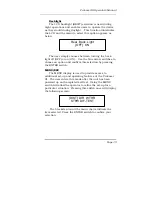
TEST/ENTER 

This is a dual purpose switch.  Pressing the 

TEST/ENTER 

push button when the unit does not have a 

menu displayed on the LCD initiates the unit’s self test.  
Pressing this button when a menu is displayed on the 
LCD enters the user’s menu selection.   

Содержание ProLaser III

Страница 1: ...er to use and service and easier to train personnel in its use These improvements include Improved range accuracy and resolution Reduced size and weight Waterproof to IP 67 and NEMA 6 Optional self contained removable long life battery pack Improved power management features with a low voltage warning and a sleep mode to conserve battery power Square reticle to define the laser beam size Inclement...

Страница 2: ...spect the shipping carton for signs of damage Any damage evident should be immediately reported to the carrier Kustom Signals Inc is not responsible for damage sustained during shipping Upon opening the carton check the contents against the following list of included items ProLaser III lidar speed detection system with corded handle 1 ea Operator s Manual Eye safety certification Accuracy calibrat...

Страница 3: ...d or focused into an extremely narrow beam for absolute target identification The signal transmitted by the ProLaser III travels in a straight line of sight as opposed to the fringing effect that is characteristic of microwave emissions The technology used by the ProLaser III to measure distances and speeds is referred to as lidar which stands for light detection and ranging When the trigger is pu...

Страница 4: ...r range operating mode D MODE ARROW MODE allows the user to select the speed measuring mode or range measuring The ARROW allows the user to navigate among the text menu items on the LCD E BRT VOL ARROW Single menu allows user to adjust the Head Up Display brightness to accommodate varying ambient light levels VOL allows the user to adjust the volume of the unit s audible alerts LCD backlight can b...

Страница 5: ...ProLaser III Operator s Manual Page 5 Figure 1 C D E F G H I B A ...

Страница 6: ...ary power to the ProLaser III Press once to turn the unit on Press and hold for one second to turn the unit off Trigger The trigger of the ProLaser III performs two functions When the trigger is pulled it activates the firing of laser pulses and the range and speed measurement functions of the system When the trigger is released the last displayed range and speed readings obtained are retained on ...

Страница 7: ...efault to speed mode MENU ESC This is a dual function switch In the Speed mode or the Range mode the primary set up menu is displayed when the push button is depressed In any menu mode depressing the button will allow the user to escape ESC to the default operating mode DISPLAYS AND INDICATORS The unit s primary display is the LCD located on the back panel of the unit In addition to speed and rang...

Страница 8: ... III is powered up The intensity of the reticle is adjusted along with the intensity of the displays by the BRT VOL switch on the rear panel of the unit Directly below the aiming reticle is a four character LED numeric display This display is used to present four types of information to the operator 1 Upon power up or the activation of the test function the HUD display will first go through a disp...

Страница 9: ...eeds and to monitor critical operating conditions without having to divert attention from the target vehicle and its surroundings STATUS DISPLAYS The ProLaser III provides user alerts on the LCD back panel They are listed below Low Voltage Alert if internal battery voltage falls below 9 2 volts When the LV Alert appears and an internal battery installed it is an indication the unit will shortly ex...

Страница 10: ... for further details SETUP There are several factors to be taken into account when setting up to make speed or distance measurements with the ProLaser III They have to do with the location of the instrument relative to the roadway upon which traffic is moving and with the actual setup in or around the patrol car In selecting a location for monitoring traffic be aware that the ProLaser III is subje...

Страница 11: ...ndicular distance from the roadway this corresponds to an angle of 5 7 or less and the amount of cosine error will not exceed 1 2 For example setting up 20 feet off the roadway and measuring targets at a range of 200 feet or greater will assure that the cosine effect produces no more than 1 2 error in the speed measurement Again it is important to remember that any cosine error introduced always r...

Страница 12: ... operating in bright daylight or in total darkness To obtain maximum operating range at the setup location the instrument should ideally be positioned so that it is not operating through any glass in the patrol vehicle The oblique angles of most windshields will often reduce the effective range of the system and in addition some windshields are treated with a coating that blocks the infrared emiss...

Страница 13: ... unit will run self test This self test consists of the following text messages Internal External Memory Tests performs a check of the contents of the memory chips in which the microprocessor programs reside Programmable Options Test Checks for corruption of the unit s configuration memory Self Test Int RAM PASS Self Test Ext RAM PASS Self Test EEPROM PASS ...

Страница 14: ...n between two independent timing circuits to verify that the range and speed determination circuits are operating properly Program Memory Test Checks unit s programmable memory for validity Indicates unit self test is complete Self Test Checksum PASS End of Self Test 0000 Self Test TIMER PASS ...

Страница 15: ...Mode and HUD Display Selection Following the units of measure display the unit will briefly display the speed ranging mode and HUD display selection The screen appears as This display indicates that the unit is in the normal speed measuring operating mode and the HUD will display speed data Default Display Upon initial power up the unit will default to speed mode and display the following If the u...

Страница 16: ...E The ARROW segment of the push button becomes functional when an operator menu item is selected as outlined in the MENU ESC switch description To return to the speed mode depress the MODE switch again Both Speed and Range will again be displayed on the LCD and the HUD will display speed measurements BRT VOL Arrow This switch is used to adjust the brightness of the HUD s display the audio volume a...

Страница 17: ...f the aiming reticle for targeting purposes To adjust press ENTER at the BRT VOL menu while HUD is selected There are eight LCD blocks between the MIN and MAX text on the LCD screen This corresponds to eight brightness levels in the HUD HUD brightness can be increased by depressing the blue arrow switch pointing upward or decreased by pressing the blue arrow switch that is pointing downward Once t...

Страница 18: ...also used to alert the operator to certain conditions such as an internal test failure existence of low battery voltage or confirmation the unit is powering down The audible alert volume VOL can be adjusted in the same manner as the HUD brightness The screen appears as below There are six 6 LCD blocks corresponding to the volume level of the audio annunciator Use the blue arrow switches to adjust ...

Страница 19: ...an option and confirm this selection by pressing the ENTER switch MENU ESC The MENU display is used to provide access to additional set up and operating features of the ProLaser III The user enters this mode after the unit has been powered up and completed self test Using the MENU switch will allow the operator to refine the set up for a particular situation Pressing this switch once will display ...

Страница 20: ... of the MIN menu item the following screen appears The blue arrow switches on the unit are then used to increase and decrease the minimum range setting The distance changes in one 1 foot or one meter increments When the desired minimum distance setting is achieved press the ENTER switch This action will return you to the main menu Maximum Distance Display and Control Selecting the maximum distance...

Страница 21: ... desired value is displayed press ENTER to set the maximum range With these settings any target that provides an adequate signal return will be displayed up to a maximum range of 6000 feet The distance to the target must be greater than 10 feet for the ProLaser III to display a reading in either Speed or Range Mode Each time the ProLaser III is powered up the maximum range control setting will def...

Страница 22: ...r III will display speeds for all vehicles Weather WTHR Menu The weather feature is used to improve the unit s sensitivity and performance in adverse weather conditions Fog rain snow and heavy dust can sometimes interfere with the performance of the ProLaser III Target ranges less than anticipated may be displayed typically between 50 250 feet Inability for the unit to lock a valid speed is a symp...

Страница 23: ...s the PWR switch on the back panel and allow the instrument to complete the self test sequence Although the internal test performs a complete check of the ProLaser III s range and speed processing circuitry you may occasionally want to test the instrument against an external standard First check the alignment of the HUD aiming reticle Select an isolated target about 100 or more feet 30 meters away...

Страница 24: ...nts the number of target distances selected in 1 above S D DE T 1 6 The standard deviation shall be less than 5 ft Differential Distance Test DIF TEST NOTE Metric units are not equipped with this feature Prepare two flat targets painted with a flat white paint plywood or particle board are suitable Place the targets at two precisely known integer feet distances along the same line of sight Use who...

Страница 25: ...I will have achieved a satisfactory calibration check if the reported speed is within 1 unit simulated MPH of twice the actual measured target range difference For example if the targets were placed at exactly 79 feet and 39 feet with a final separation of 40 feet the final speed reading on the ProLaser III must be 79 80 or 81 If the ProLaser III does not pass the test recheck the target mounts di...

Страница 26: ...instrument is squarely aimed at a moving target and is processing valid speed data the tone will become constant At this point the target speed will appear on the HUD in place of the dashes and on the rear panel under the Speed The speed indication will be preceded by a sign if the target is receding and by a sign in the rear panel display or no sign in the HUD if the target is approaching As long...

Страница 27: ...icle to aim the instrument at the desired target and pull and hold the trigger You will see a series of four dashes directly below the aiming reticle while the laser is firing and range measurements are being made After approximately 0 3 second the distance to the target will appear both in the HUD and under the Range text in the rear panel LCD Distances will be displayed to the nearest 0 1 feet m...

Страница 28: ...es not measure distances shorter than 10 feet Aiming the ProLaser III at objects closer than 10 feet will not produce a range or speed display Stopwatch Mode The stopwatch mode of the ProLaser III is used to calculate average speed based on the elapsed time taken by a vehicle to travel a predetermined distance To use the stopwatch mode press the MENU switch and use the blue arrow switches to move ...

Страница 29: ...sure to be used in the stopwatch mode Either selection will summon a distance entry screen that appears below Using the blue arrow switches enter the distance the target vehicle will be traveling during the measurement The minimum range that can be used is 300 feet Depress ENTER to confirm your selection Once the ENTER switch is pushed the Audio On Off screen will appear The screen looks like Ente...

Страница 30: ...timing function The calculated average speed will be shown under Speed in the LCD display window and the time in tenths of a second will be shown under Time on the LCD Note that the time elapsed is shown in the HUD until the speed is calculated and then the calculated speed is shown in the HUD Stopwatch Measure Mode In addition to the enter distance mode the unit allows the operator to calculate a...

Страница 31: ...n the area next to Dist2 After a suitable range is obtained press ENTER Note that Distance too short appears if the range difference is less than 300 feet The difference between the two ranges will appear on a screen as below NOTE The operator and the two aiming points must be in a straight line for the distance measurements to be accurate The user can increase or decrease this range using the uni...

Страница 32: ...ation this might be used to display or store speed readings from the ProLaser III The connector used for this signal is a 6 pin DIN style circular connector if you have trouble obtaining a compatible plug locally the mating part can be ordered through Kustom Signals Customer Service Department POWER CONSERVATION FEATURES After approximately one minute with no activity the ProLaser III will enter a...

Страница 33: ...age Alert or Low Voltage Warning will appear on the display unscrew from the handle of the ProLaser III and recharge by inserting it into the charger and attaching it the same way as is done in the handle Plug the charger into a wall outlet and allow to charge for 4 5 hours standard charger When the battery pack is fully charged the charger will cease charging in order not to harm the battery pack...

Страница 34: ...may be cleaned include the laser output aperture the HUD combiner glass and the HUD lens Gently brush loose debris from the optical surface to be cleaned Then using a clean lint free cloth or lens cleaning tissue dampened with low residue isopropyl alcohol gently wipe the optical surface with a circular motion A cotton swab may facilitate cleaning of the HUD lens and the lower surface of the HUD c...

Страница 35: ...tion of the sensitive receiver resulting in loss of performance 4 Contact KSI for periodic calibration requirements TROUBLESHOOTING PROCEDURES In the event of suspected instrument malfunction double check the setup and operational procedures as well as the power source If all these appear satisfactory and the ProLaser III still does not perform properly it should be returned to the Kustom Signals ...

Страница 36: ... laser products sold in the US The ProLaser III is certified as a Class I device in accordance with the safety standards of CDRH Class I is the lowest classification of laser product in terms of relative potential risk A good description of this category is provided by the Laser Institute of America as follows Class I A Class I laser is considered safe based upon current medical knowledge This cla...

Страница 37: ...ed period of time Prescription eyeglasses bifocals and so on are not considered optical gain devices because they serve only to correct the focus of the eye to normal human vision In all respects of normal operation excluding intentional abuse the ProLaser III is completely safe for human exposure Persons interested in receiving further information regarding laser safety regulations are encouraged...

Страница 38: ...has been tested and found to comply with the limits for a Class A digital device pursuant to Part 15 of FCC Rules These limits are designed to provide reasonable protection against harmful interference in a commercial installation This equipment generates uses and can radiate radio frequency energy and if not installed and used in accordance with the instructions may cause harmful interference to ...

Страница 39: ... Idle Sleep Power Down ALERT Low voltage WARNING Lo volt Battery Voltage VDC Current ma 13 6 510 13 6 520 13 6 300 13 6 130 13 6 3 9 2 VDC nom 8 6 VDC nom 9 6 VDC nom NiMH Operating Temperature 30 to 60 C 22 to 140 F 90 relative humidity 37 C non condensing Dimensions 7 36 L x 4 21 W x 9 92 H including handle and heads up display Weight 3 lb Eye Safety CDRH Class One Eyesafe ...

Страница 40: ... Accuracy 6 inches 15 m one standard deviation when target is on a flat white or gray surface Beam Width 3 ft X 3ft at 1000feet 3 m X 3m at 1000 meters 3 0 mr vertical x 3 0 mr horiz Acquisition Time typ 0 3 second for 60 mph target Auxiliary Output Outputs speed and range data Operational Speed Accuracy Test Depress the trigger just before the target reaches the first baseline and release it just...

Страница 41: ...Owner s or Lessee s exclusive remedy under this Warranty is limited to repair to the manufacturer s operational specifications or replacement at the sole discretion of Kustom Signals Inc or its agent of the Equipment as i is covered by this Warranty ii is delivered to Kustom Signals Inc or its agent at the Owner s or Lessee s expense within the term of this Warranty and iii upon examination thereo...

Страница 42: ...ment which has been defaced or damaged through normal usage The liability of Kustom Signals Inc if any with respect to the equipment shall be limited as provided in this Warranty Kustom Signals Inc disclaims any obligation or liability for the loss of use of the Equipment warranted loss of time inconvenience commercial loss or other direct consequential special or incidental damages Kustom Signals...

Страница 43: ... non rechargeable batteries light bulbs transmitter carrying pouch and microphone cables w microphone and windscreen are considered consumable items and as such are not covered by this warranty SMART Radar SMART system radar units are warranted for two years subject to the warranty terms listed above ...

Страница 44: ......

Страница 45: ...MODE Arrow 7 MENU ESC 7 Displays and Indicators 7 Heads Up Display 8 Status Displays 9 Operation 10 Setup 10 Power On Sequence 13 Mode Option Selection 16 Mode 16 BRT VOL 16 Brightness 17 Volume 18 Backlight 19 MENU ESC 19 Distance 20 Direction 21 Weather 22 Stopwatch 23 Differential Distance 23 Accuracy Tests 23 Operating Procedures 26 Speed Mode 26 Range Mode 27 Stopwatch Mode 28 ...

Страница 46: ...ns 39 Warranty 41 Copyright 1999 Kustom Signals Inc All Rights Reserved Printed in USA This publication may not be reproduced stored in a retrieval system or transmitted in whole or in part in any form or by any means electronic mechanical photocopying recording or otherwise without prior written permission of Kustom Signals Inc 9325 Pflumm Lenexa KS 66215 3347 Customer Service 800 835 0156 Sales ...

Страница 47: ...PRO LASER III REFERENCE MANUAL 1010 W Chestnut P O Box 947 Chanute KS 66720 KPN 006 0605 00 Rev 3 ...

Отзывы: