background image

42

Teil 1 - MONTAGEHINWEISE

3 - Befestigung des Kamins

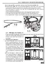
a) Die  Befestigungsschrauben 

M

der  beiden  Kaminteile  lockern
und  den  inneren  Teil  I  fast  zur
Gänze  herausziehen  (

Abb.  20

).

Die Schutzfolie 

P

 abziehen.

b) Den  unteren  Kaminteil  in  seiner

Aufnahme  oben  am  Kamin
einsetzen.  Die  Gebläsegruppe
bis 

zum 

Wandblech 

S

herunterlassen  und  mit  der  mitgelieferten
Schraube 

H

 anschrauben (

Abb. 21

). Den der

Lieferung  beigefügten  Deckel 

D

  am

Wandblech 

S

 montieren (

Abb. 22

).

c) Die Dichtung 

G1

 (im Zubehörbeutel) an der

Basis  des  Kamins 

A

  fixieren,  wobei  diese

perfekt auf dem Profil des Kamins 

A

 aufliegen

muss. Dann den Kamin 

A

 mit Hilfe von vier

mitgelieferten Schrauben am Haubenkorpus

C

 fixieren 

E

  (

fig. 23

).

d) Die  der  Lieferung  beigefügte  durchsichtige

Dichtung 

Q

  einfügen,  damit  zwischen  den

beiden Kaminteilen kein Spiel besteht (

Abb. 24

).

Die M-Schrauben anziehen.

e) Die Haltestante 

B

 entfernen.

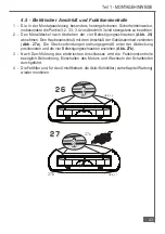
4.4  -  Anschluß  Abluft-  oder  Umluftbetrieb

1 - Anschluß im Abluftbetrieb.

Für sämtliche Installationsarten:

a) Den Luftabgang an das Außenrohr anschließen.
b) Den  eventuell  im  Haubenkörper  eingesetzten

Aktivkohlefilter entfernen (siehe Kapitel Wartung).

2 - Anschluß im Umluftbetrieb

Ausschließlich  für  die  Installation  mit  nach  oben
gerichtetem Luftabgang. Das Luftgitter G am Luftabgang
montieren (

Abb. 25

). Der Aktivkohlefilter darf erst nach Ausführung

des elektrischen Anschlusses im Haubenkörper eingesetzt werden.

E

E

E

E

A08_TL

A

G1

C

2 1

2 1

2 2

2 2

2 3

2 3

2 4

2 4

2 5

2 5

Содержание KD 674.1 GE

Страница 1: ...ageanweisungen Instructions for use and installation instructions Instructions d utilisation et avis de montage Gebruiksaanwijzing en montagehandleiding Istruzioni di uso e di montaggio Instrucciones de uso y de montaje KD 674 1GE KD 974 1GE ...

Страница 2: ......

Страница 3: ...ENZIONE 13 3 1 Filtri antigrasso metallici 14 3 2 Filtro al carbone attivo 14 3 3 Illuminazione 15 3 4 Pulizia 15 1 GENERAL DATA 16 2 COMPONENTS 16 3 SAFETY WARNINGS 16 4 INSTALLATION 17 4 1 Selecting the type of installation 17 4 2 Installation of the hood canopy C 18 4 3 Installation of the chimney A 20 4 4 Ducting or recirculation fitting 22 4 5 Connection to power supply and checking of good w...

Страница 4: ...E 33 2 UTILISATION 33 3 ENTRETIEN 33 3 1 Filtres métalliques anti graisse 34 3 2 Filtre au charbon actif 34 3 3 Eclairage 35 3 4 Nettoyage 35 1 ALLGEMEINES 36 2 BAUELEMENTE 36 3 SICHERHEITSHINWEISE 36 4 MONTAGE 37 4 1 Wahl der Installationsart 38 4 2 Montage des Haubenkörpers C 38 4 3 Montage des Kamins A 40 4 4 Anschluß Abluft oder Umluftbetrieb 42 4 5 Elektrischer Anschluß und Funktionskontrolle...

Страница 5: ...filters 55 3 2 Actief koolstoffilter 55 3 3 Verlichting 56 3 4 Reiniging 56 1 GENERALIDADES 57 2 COMPONENTES 57 3 ADVERTENCIAS DE SEGURIDAD 57 4 INSTALACION 58 4 1 Eleccion del tipo de instalacion 58 4 2 Instalación del cuerpo de la campana C 59 3 Montaje del cuerpo de la campana C en la pared 60 4 3 Instalación de la chimenea A 61 4 4 Conexión aspiradora o filtradora 63 4 5 Conexión eléctrica y c...

Страница 6: ...elescopico A completo di gruppo aspira tore 2 3 n 1 flangia Ø 120 o Ø 150 F 2 4 n 1 griglia direzionata G 2 5 n 1 raccordo R 2 6 n 1 asta di sostegno B 2 7 n 1 sacchetto contenente n 1 staffa S per il fissaggio del camino n 1 coperchio D viti tasselli e documenti 3 AVVERTENZE PER LA SICUREZZA 3 1 Non collegare l apparecchio a condotti di scarico dei fumi prodotti da combustione caldaie caminetti e...

Страница 7: ... alto Installazione filtrante o aspirante 2 Uscita dell aria rivolta verso la parete solo installazione aspirante 3 Uscita dell aria rivolta verso destra o sinistra solo installazione aspirante Per installare la cappa correttamente deve essere seguito il seguente schema 4 1 Scelta del tipo di installazione 4 2 Installazione del corpo cappa C 4 3 Installazione del camino A 4 4 Connessione aspirante...

Страница 8: ...on una punta Ø8 mm forare i punti segnati b Nel caso di installazione con uscita dell aria rivolta verso la parete fig 5a é necessario effettuare la foratura per l eva cuazione dell aria Ø120 o 150 mm in funzione del diame tro della flangia F in dotazione 2 Montaggio degli elementi di fissaggio a Inserire i tasselli in dotazione nei fori 1 e 2 b Montare gli occhielli O fig 6 c Fissare la staffetta...

Страница 9: ...rete fig 10 e Regolazione assetto fig 11 La cappa é fornita nella parte posteriore di due ag ganci regolabili per regolarne l assetto operare come segue Ruotare le viti L fino a far coincidere le viti N con i fori di accesso inferiori Ruotare le viti N per regolare la posizione verticale e orizzontale della cappa Serrare le viti L per bloccare la cappa contro la parete Inserire nei fori di accesso...

Страница 10: ... effettuare un ade guata foratura sulla sola mensola supe riore per l attraversamento della tuba zione di evacuazione dell aria fig 13 2 Orientamento e predisposizione del gruppo aspiratore a La cappa di serie viene fornita con l usci ta dell aria orientata verso la parete fig 3 nel caso di installazione con uscita dell aria rivolta verso dx o sx fig 4a b é necessario modifica re l orientamento de...

Страница 11: ...e la pellicola protettiva P b Appoggiare la parte inferiore del camino nel suo alloggiamento sulla sommità della cappa Abbassare il gruppo aspiratore fino alla staffetta S e fissarlo con la vite H in dotazione fig 21 Montare il coperchio D in dotazione sulla staffetta S fig 22 c Inserire la guarnizione G1 contenuta nel sacchetto ac cessori sulla base del camino A facendo in modo che la stessa ader...

Страница 12: ...ffettuato la connessione elettrica 4 5 Connessione elettrica e controllo funzionale 1 È necessario rispettare scrupolosa mente le avvertenze 3 2 3 3 e 3 4 del paragrafo 3 relative alla sicurez za 2 Smontare il coperchio metallico to gliendo le due viti di fissaggio ester ne fig 26 Collegare la connessio ne della cappa alla connessione del gruppo motore fig 27a Posizio nare correttamente i connetto...

Страница 13: ... rispetto al fondo delle pentole si risparmia energia e si evitano pericolose concentrazioni di calore 1 4 Non fare mai un uso improprio dell apparecchio che è stato progettato esclusivamente per abbattere gli odori in cucina 2 USO Quadro comandi fig 28 Lo schema dei comandi è il seguente TASTO Accende e spegne l impianto di illuminazione TASTO Accende e spegne il motore TASTO Diminuisce la veloci...

Страница 14: ...me operare come segue Spegnere le luci e il motore di aspirazione Premere il tasto Velocità per almeno 3 secondi sino al lampeggio di conferma dei leds ATTENZIONE è necessario rispettare i tempi di manutenzione o sostituzione indicati per evitare un possibile rischio di incendio se i filtri si saturano di grassi 3 2 Filtro al carbone attivo 1 Funzionamento Il filtro al carbone attivo é presente so...

Страница 15: ...ue Premere il tasto Velocità per almeno 3 secondi sino al lampeggio di conferma dei leds In tutti i casi la segnalazione di allarme saturazione filtri si verifica solo quando é azionato il motore aspirazione ATTENZIONE è necessario rispettare i tempi di manutenzione o sostituzione indicati per evitare un possibile rischio di incendio se i filtri si saturano di grassi 3 3 Illuminazione 1 È costitui...

Страница 16: ...g spigot R 2 6 No 1 support rod B 2 7 No 1 fixing kit containing No 1 wall bracket S to fix the canopy hood No 1 cover D screws rawl plugs and documentation 3 SAFETY WARNINGS 3 1 When used in the extraction mode the cooker hood ducting must not be connected to a flue which is used for exhausting fumes from appliances supplied with energy other than electric such as a central heating flue or water ...

Страница 17: ...fan unit on this hood enables it to be installed in one of four different ways 1 Air outlet directed upwards ducting or recirculation fitting 2 Air outlet directed towards the wall ducting fitting only 3 Air outlet directed to the right or left ducting fitting only For correct installation of the hood please proceed in the following stages 4 1 Selection of the type of installation 4 2 Installation...

Страница 18: ...on Z of the chimney required for installation plus 11 mm X Z 18 7 Using a Ø8 mm drill bit drill the points marked in this way b When installed with the air outlet directed towards the wall fig 5a it will be necessary to drill an air ducting opening measuring Ø120 or 150 mm according to the diameter of the flange F provided 2 Fitting the fixing elements a Insert the rawl plugs provided into holes 1...

Страница 19: ...ig 9 d Adjust the support rod B so that it pushes against the wall fig 10 e Adjusting position fig 11 There are two adjustable hooks at the rear of the hood which can be used to adjust its position as follows Turn the screws L until the position of screws N coincides with the lower access holes Turn the screws N to adjust the vertical and horizontal position of the hood Lock the screws L to fasten...

Страница 20: ...w the line of shelves it will be necessary to drill a suitable hole in the top shelf only to allow the air ducting pipe to pass through fig 13 2 Direction and position of the ducting fan unit a The hood is normally supplied with the air towards the wall installed with the to the right or left be necessary to change of the ducting fan proceeding as follows Unscrew the screws Turn the ducting the ri...

Страница 21: ...ll the way out Remove the protective film P b Rest the lower section of the chimney in its housing on the top of the hood canopy Lower the ducting fan unit until it reaches the wall bracket S and fix it using the screw H provided fig 21 Fit the cover D provided on the wall bracket S fig 22 c Insert gasket G1 found in the accessory bag on the base of chimney stack A so that it adheres perfectly to ...

Страница 22: ...y after connection to the power supply 4 5 Connection to power supply and checking of good working order 1 It is absolutely necessary to follow the warnings 3 2 3 3 and 3 4 of paragraph 3 concerning safety measures 2 Loosen the two locking screws and remove the metal cover fig 26 Connect the hood connection to the engine connection fig 27a Correctly place the connectors under the cover and tighten...

Страница 23: ...rom licking round from the bottom of the pan this will save energy and will avoid a dangerous concentration of heat 1 4 Always ensure that the appliance is used in accordance with the manufacturer s instructions for the removal of contaminated air and odours during cooking 2 OPERATION Control Panel fig 28 The layout of the control panel is as follows Key Turns the lighting system on and off Key Tu...

Страница 24: ...suction motor Press the Speed button for at least 3 seconds until the LEDs flash in confirmation In any case the saturated filters alarm will only come into operation when the suction motor is turned on WARNING always comply with the maintenance and replacement times indicated in order to avoid a possible risk of fire when the filters are saturated with grease 3 2 Activated charcoal filter 1 Opera...

Страница 25: ...ollows Press the Speed button for at least 3 seconds until the LEDs flash in confirmation In any case the saturated filters alarm will only come into operation when the suction motor is turned on WARNING always comply with the maintenance and replacement times indicated in order to avoid a possible risk of fire when the filters are saturated with grease 3 3 Light 1 It consists of 2 20 W halogen sp...

Страница 26: ...et l éclairage 2 2 1 cheminée télescopique A comprenant le groupe d aspiration 2 3 1 bride Ø 120 ou Ø 150 F 2 4 1 grille directionnelle G 2 5 1 raccord R 2 6 1 tige de soutien B 2 7 1 sachet contenant 1 étrier S pour la fixation de la cheminée 1 couvercle D des vis des goujons et documents 3 INSTRUCTIONS POUR LA SECURITE 3 1 Ne jamais raccorder la hotte à des conduits d évacuation des fumées produ...

Страница 27: ... installation 1 Sortie de l air orientée vers le haut Installation filtrante ou aspirante 2 Sortie de l air orientée vers la paroi installation aspirante uniquement 3 Sortie de l air orientée vers droite ou gauche installation aspirante uniquement Pour installer la hotte correctement il faut suivre les instructions du schéma suivant 4 1 Choix du type d installation 4 2 Installation du corps de la ...

Страница 28: ...a cheminée Z nécessaire pour l installation plus 11 mm X Z 18 7 Avec une mèche de Ø8 mm percer en correspondance des points marqués b En cas d installation avec la sortie de l air orientée vers la paroi fig 5a il faut effectuer le perçage pour l évacuation de l air Ø120 ou 150 mm en fonction du diamètre de la bride F fournie avec l appareil 2 Montage des éléments de fixation a Insérer les goujons ...

Страница 29: ...ien B de façon à ce qu elle soit perpendiculaire à la paroi fig 10 e Réglage du positionnement fig 11 La hotte est équipée de deux crochets de fixation réglables qui se trouvent dans la partie arrière de l appareil pour en régler le positionnement effectuer les opérations suivantes Tourner les vis L jusqu à ce que les vis N coïncident avec les trous inférieurs Tourner les vis N pour régler la posi...

Страница 30: ...ctuer un perçage approprié uniquement sur l étagère supérieure pour permettre le passage du conduit d évacuation de l air fig 13 2 Orientation et préparation du groupe d aspiration a La hotte standard est fournie avec la sortie de l air orientée vers la paroi fig 3 en cas d installation avec sortie de l air orientée à droite ou à gauche fig 4a b il faut modifier l orientation du groupe d aspiratio...

Страница 31: ...n P b Poser la partie inférieure de la cheminée dans son logement sur l extrémité supérieure de la hotte Baisser le groupe d aspiration jusqu à l étrier S puis fixer celui ci au moyen de la vis H fournie avec l appareil fig 21 Monter le couvercle D fourni avec l appareil sur l étrier S fig 22 c Insérer la garniture G1 qui se trouve dans le sachet des accessoires sur la base de la cheminée A en fai...

Страница 32: ...nté après avoir effectué le branchement électrique 4 5 Branchement électrique et contrôle fonctionnel 1 Il faut absolument respecter les instructions 3 2 3 3 et 3 4 du paragraphe 3 concernant la sécurité 2 Démonter le couvercle métallique en enlevant les vis de fixation fig 26 Brancher la connexion de la hotte à la connexion du groupe moteur fig 27a Positionner correctement les connecteurs sous le...

Страница 33: ... par rapport au fond des marmites vous économisez de l énergie et vous évitez de dangereuses concentrations de chaleur 1 4 N utilisez jamais incorrectement votre appareil qui est destiné uniquement à abattre les odeurs dans la cuisine 2 UTILISATION Tableau des commandes fig 28 Le schéma des commandes est le suivant Touche Allume et éteint le circuit d éclairage Touche Allume et éteint le moteur To...

Страница 34: ...ppuyer sur la touche Vitesse pendant 3 secondes au moins jusqu au clignotement de confirmation des leds Dans tous les cas la signalisation d alarme saturation des filtres ne se vérifie que lorsque le moteur d aspiration est actionné ATTENTION il est nécessaire de respecter les temps indiqués d entretien ou de remplacement pour éviter un risque possible d incendie si les filtres se saturent de grai...

Страница 35: ...secondes au moins jusqu au clignotement de confirmation des leds Dans tous les cas la signalisation d alarme saturation filtres ne se vérifie que lorsque le moteur d aspiration est actionné ATTENTION il est nécessaire de respecter les temps indiqués pour l entretien ou le remplacement pour éviter des risques possibles d incendie si les filtres se saturent de graisses 3 3 Eclairage 1 Il est constit...

Страница 36: ...1 Flansch Ø 120 oder Ø 150 F 2 4 1 gerichtetes Luftgitter G 2 5 1 Adapter R 2 6 1 Haltestange B 2 7 1 Polybeutel mit 1 Wandblech S zur Befestigung des Kamins 1 Deckel D Schrauben Dübel und Unterlagen 3 SICHERHEITSHINWEISE 3 1 Die Dunstesse nicht an Rauch oder Abgaskamine anschließen die noch für offene Feuerstellen benutzt werden Bei der Ableitung von Abluft sind die behördlichen Bestimmungen zu b...

Страница 37: ...iner raumluftabhängiger Feuerstätte wie z B gas öl oder kohlebetriebene Heizgeräte Durchlauferhitzer Warmwasserbereiter ist Vorsicht geboten da beim Absaugen der Luft durch die Dunstabzugshaube dem Aufstellraum die Luft entnommen wird die die Feuerstätte zur Verbrennung benötigt Ein gefahrloser Betrieb ist möglich wenn bei gleichzeitigem Betrieb von Haube und raumluftabhängiger Feuerstätte ein Unt...

Страница 38: ...ntage des Haubenkörpers C 1 Durchbohrung der Wand a Die Mittelpunkte der Bohrlöcher 1 zur Befestigung des Haubenkörpers C unter Verwendung der Pappenschablone auf der Wand anzeichnen Der Mittelpunkt des Bohrloches 2 zur Befestigung des Kamins Abb 5a Luftabgang nach oben oder nach außen Abb 5b c Luftabgang nach rechts oder links ist in einem Abstand X von der Zwischenachse der Bohrlöcher 1 anzuzeic...

Страница 39: ...übel in die Bohrlöcher 1 und 2 einführen b Die Ösen O Abb 6 montieren c Unter Verwendung der mitgelieferten Schraube V das Wandblech S im Bohrloch 2 festspannen Abb 7 3 Wandmontage des Haubenkörpers C a Etwa eingesetzte Fettfilter und Aktivkohlefilter entfernen vgl hierzu den Abschnitt Wartung b Unter Verwendung der zwei mitgeliefertern Schrauben K 3 5x9 5 die Haltestange B montieren Abb 8 c Den H...

Страница 40: ...Kamins A Etwa vorhandene Holzplatten im Montagebereich der Haube sind auf jeden Fall bei jeder Art von Montage abzubauen zu bohren und dann erst wieder zu montieren 1 Bohrung der Holzplatten a In den Holzplatten unter Verwendung einer Pappenschablone und unter Bezugnahme auf das Bohrloch B der mittleren Achse entlang eine Bohrung zur Durchführung des Kamins auszuführen Der Haubenköper ist vor der ...

Страница 41: ... Installation vorzurüsten Luftabgang nach oben Abb 2a b Den Plastikverschluß vom oberen Gebläseteil abnehmen und ihn rückseitig anbringen Abb 15 Luftabgang zur Wand Abb 3 Den Kunststoffrahmen vom Luftabgang entfernen Abb 16 Den Verschluß vom oberen Teil der Gebläsegruppe abnehmen Abb 17 damit der Flansch F eingeführt werden kann Den Flansch F Ø120 oder 150 mm Abb 18 montieren und den Verschluß F w...

Страница 42: ... vier mitgelieferten Schrauben am Haubenkorpus C fixieren E fig 23 d Die der Lieferung beigefügte durchsichtige Dichtung Q einfügen damit zwischen den beiden Kaminteilen kein Spiel besteht Abb 24 Die M Schrauben anziehen e Die Haltestante B entfernen 4 4 Anschluß Abluft oder Umluftbetrieb 1 Anschluß im Abluftbetrieb Für sämtliche Installationsarten a Den Luftabgang an das Außenrohr anschließen b D...

Страница 43: ...ehmen Den Haubenanschluß mit dem Anschluß der Gebläseeinheit verbinden Abb 27a Die Steckverbindungen ordnungsgemäß unter der Abdeckung positionieren und die vier Befestigungsschrauben anziehen Abb 27b 3 Nach Durchführung des elektrischen Anschlusses wird die Funktionskontrolle bezüglich Beleuchtung Einschalten des Motors und Wechseln der Schaltstufen durchgeführt 4 Die Fettfilter und für den Umluf...

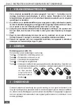
Страница 44: ...usbreitet Man spart auf diese Weise Energie und vermeidet eine gefährliche Hitzekonzentration 1 4 Die Dunstabzugshaube ist ausschließlich zum Absaugen von Küchengerüchen vorgesehen Bei nicht bestimmungsgemäßer Benutzung erlischt jede Hersteller Garantie 2 Betrieb Bedienfeld Abb 28 Folgende Bedientasten stehen zur Verfügung Taste Ein und Ausschalten der Beleuchtung Taste Ein und Ausschalten des Mot...

Страница 45: ... den Gebläsemotor ausschalten Die Taste Gebläsestufe mindestens 3 Sekunden lang gedrückt halten bis die Leds zu blinken beginnen Zu beachten ist dass dasAlarmsignal für die Filtersättigung nur dann gegeben wird wenn der Gebläsemotor eingeschaltet ist ACHTUNG die Zeitintervalle für Wartung und Austausch der Filter müssen unbedingt eingehalten werden da bei fettgesättigten Filtern Brandgefahr besteh...

Страница 46: ...n bis die Leds zu blinken beginnen Zu beachten ist dass dasAlarmsignal für die Filtersättigung nur dann gegeben wird wenn der Gebläsemotor eingeschaltet ist ACHTUNG die Zeitintervalle für Wartung undAustausch der Filter müssen unbedingt eingehalten werden da bei fettgesättigten Filtern Brandgefahr besteht 3 3 Beleuchtung 1 Die Beleuchtung besteht aus 2 Halogenlampen von je 20 W 2 Wechsel der Lampe...

Страница 47: ...asemkap C met bedieningspaneel en verlichting 2 2 1 telescopische schouw A met afzuigunit 2 3 1 flens Ø 120 of Ø 150 F 2 4 1 gericht roostertje G 2 5 1 verbindingsstuk R 2 6 1 draagstang B 2 7 1 zakje met inhoud 1 beugel S voor bevestiging van de wasemkap 1 deksel D schroeven pluggen en documenten 3 VEILIGHEIDSMAATREGELEN 3 1 Sluit het apparaat niet aan op pijpen die door verbranding ontstane rook...

Страница 48: ...tallatie voor filteren van de lucht of afvoer van de lucht naar buiten 2 Luchtuitgang naar de wand gericht alleen afvoer van de lucht naar buiten 3 Luchtuitgang naar rechts of links gericht alleen installatie met afvoer van de lucht naar buiten Om de wasemkap correct te installeren moet het volgende schema worden gevolgd 4 1 Keuze van het type installatie 4 2 Installatie van de wasemkap C 4 3 Inst...

Страница 49: ...aald door de extensie van de schouw Z te meten die nodig is voor de installatie plus 11 mm X Z 18 7 Boor de getekende gaten met een boorpunt Ø8 mm b In het geval van installatie met de luchtuitgang naar de wand gericht fig 5a moet het gat worden geboord om de lucht door af te voeren Ø120 of 150 mm al naar gelang de diameter van de bijgeleverde flens F 2 Montage van de bevestigingselementen a Steek...

Страница 50: ...fig 9 d Regel de draagstang B zo dat hij tegen de muur duwt fig 10 e Uitlijning fig 11 Aan de achterkant van de wasemkap zitten twee verstelbare haken om de uitlijning als volgt in te stellen Draai de schroeven L totdat de schroeven N samenvallen met de onderste toegangsopeningen Draai de schroeven N om de verticale en horizontale positie van de wasemkap te regelen Span de schroeven L om de wasemk...

Страница 51: ...rdt geïnstalleerd een geschikt gat worden geboord in de bovenste plank om de afvoerleiding van de lucht door te leiden fig 13 2 Richten en voorbereiding van de afzuigunit a De standaard wasemkap wordt geleverd met de luchtuitgang naar de wand gericht fig 3 bij installatie met de luchtuitgang naar links of rechts gericht fig 4a b moet de richting van de afzuiger worden veranderd als volgt Draai de ...

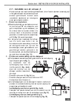
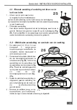
Страница 52: ... haal het binnenste deel I fig 20 bijna helemaal naar buiten Verwijder het beschermfolie P b Zet het onderste schouwdeel in de behuizing boven op de wasemkap Laat de afzuigunit zakken tot het beugeltje S en zet hem vast met de bijgeleverde schroef H fig 21 Monteer het deksel D bijgeleverd op het beugeltje S fig 22 c Voeg het verbindingsstuk G1 in het zakje met accessoires op de basis van de schouw...

Страница 53: ... gebracht 4 5 Elektrische aansluiting en controle van de werking 1 De onder punt 3 2 3 3 en 3 4 van paragraaf 3 aangegeven waarschuwingen betreffende de veiligheid moeten nauwgezet in acht worden genomen 2 Demonteer het metalen deksel door de vier bevestigingsschroeven te ontschroeven fig 26 Verbind de aansluiting van de wasemkap met de aansluiting van de motorunit fig 27a Plaats de verbindingspun...

Страница 54: ...nt van de pan uit komt hierdoor bespaart u energie en voorkomt u gevaarlijke warmteconcentraties 1 4 Gebruik het apparaat niet voor oneigenlijke doeleinden het apparaat is uitsluitend ontworpen om keukenluchtjes tegen te gaan 2 GEBRUIK Bedieningspaneel Afb 28 Het schema van de bedieningen is als volgt Toets Schakelt de verlichting aan en uit Toets Schakelt de motor aan en uit Toets Vermindert de z...

Страница 55: ...ichting en de afzuigmotor uit Druk gedurende minstens 3 seconden op de toets Snelheid totdat alle leds gaan knipperen ter bevestiging In alle gevallen wordt het alarm van verzadigde filters alleen gegeven als de afzuigmotor ingeschakeld is LET OP de aangegeven tijden voor onderhoud of vervanging moeten in acht genomen worden om mogelijk brandgevaar te vermijden als de filters verzadigd zijn met ve...

Страница 56: ...tdat de leds knipperen ter bevestiging In alle gevallen wordt het alarm van verzadigde filters alleen gegeven als de afzuigmotor ingeschakeld is LET OP de aangegeven tijden voor onderhoud of vervanging moeten in acht genomen worden om mogelijk brandgevaar te vermijden als de filters verzadigd zijn met vet 3 3 Verlichting 1 Bestaat uit 2 halogeenspots van 20 W 2 Vervanging fig 31 Verwijder de twee ...

Страница 57: ...0 F 2 4 n 1 rejilla orientada G 2 5 n 1 racor R 2 6 n 1 barra de soporte B 2 7 n 1 sobre que contiene n 1 abrazadera S para la fijación de la chimenea n 1 tapa D tornillos tarugos y documentos 3 ADVERTENCIAS DE SEGURIDAD 3 1 No conectar el aparato a tuberías de evacuación de humos causados por combustión calderas chimeneas etc 3 2 Verificar que la tensión de la red corresponda a la indicada en la ...

Страница 58: ...a la pared sólo instalación aspiradora 3 Salida del aire dirigida hacia la derecha o la izquierda sólo instalación aspiradora Para instalar la campana correctamente debe seguirse el siguiente esquema 4 1 Elección del tipo de instalación 4 2 Instalación del cuerpo de la campana C 4 3 Instalación de la chimenea A 4 4 Conexión aspiradora o filtradora 4 5 Conexión eléctrica y control funcional 4 1 Ele...

Страница 59: ...diendo la extensión de la chimenea Z necesaria para la instalación más 11 mm X Z 18 7 Con una broca Ø8 mm perforar los puntos marcados b Si se trata de una instalación con salida del aire dirigida hacia la pared fig 5a es necesario hacer un orificio para la evacuación del aire de 120 o 150 mm de diámetro según el diámetro de la brida F en dotación 2 Montaje de los elementos de fijación a Introduci...

Страница 60: ...a de soporte B de manera que quede contra la pared fig 10 e Regulación del equilibrio fig 11 La campana tiene en la parte posterior dos enganches ajustables para regular el equilibrio operar de la siguiente manera Hacer girar los tornillos L hasta hacer coincidir los tornillos N con los orificios de acceso inferiores Hacer girar los tornillos N para regular la posición vertical y horizontal de la ...

Страница 61: ...repisa superior solamente para que atraviesen las tuberías de evacuación del aire fig 13 2 Orientación y predisposición del grupo aspirador a La campana se vende de serie con la salida del aire orientada hacia la pared fig 3 en el caso de instalación con salida de aire dirigida hacia la derecha o izquierda fig 4a b es necesario modificar la orientación del aspirador operar de la siguiente manera D...

Страница 62: ...ección P b Apoyar la parte inferior de la chimenea en su alojamiento en la cima de la campana Bajar el grupo aspirador hasta la abrazadera S y fijarlo con el tornillo H in dotación fig 21 Montar la tapa D incluida en el suministro en la abrazadera S fig 22 c Introducir la guarnición G1 que se encuentra en la bolsa de accesorios ubicada en la base de la chimenea de manera que la misma adhiera perfe...

Страница 63: ...ués de haber efectuado la conexión eléctrica 4 5 Conexión eléctrica y control funcional 1 Es necesario respetar escrupulosamente las indicaciones dadas en los puntos 3 2 3 3 3 4 del párrafo 3 que trata la seguridad 2 Desmontar la tapa metálica quitando los dos tornillos que la sujetan fig 26 Unir la conexion de la campana con la del motor fig 27a Colocar correctamente los contactos debajo de la ta...

Страница 64: ...rde de la cazuela de esta manera se ahorra energía y se evitan condensaciones de calor peligrosas 1 4 No hacer uso impropio de la campana se debe tener en consideración que ha sido creada únicamente para evitar los malos olores en la cocina 2 USO Tablero de mandos fig 28 El esquema de mandos es el siguiente TECLA Enciende y apaga la instalación de iluminación TECLA Enciende y apaga el motor TECLA ...

Страница 65: ...ión Apretar la tecla Velocidad durante tres segundos hasta que se enciendan y se apaguen los pilotos De todas maneras la señal de alarma debida a la saturación de los filtros se produce solo cuando el motor de aspiración esta encendido ATENCION Respetar los periodos de mantenimiento indicados Se evitara de dicha manera que los filtros prendan fuego debido a la saturación de grasa 3 2 Filtro de car...

Страница 66: ...ecla Velocidad durante tres segundos hasta que se enciendan y apaguen los pilotos De todas maneras la señal de alarma debida a la sauración de los filtros se produce solo cuando el motor de aspiración esta encendido ATENCION Respetar los periodos de matenimiento indicados Se evitara de dicha manera que los filtros prendan fuego debido a la saturación de grasa 3 3 Iluminación 1 Esta formada por dos...

Страница 67: ... revendeur auprès duquel vous avez acheté l appareil vous en communiquera les dispositions particulières Pour l application de la garantie il est nécessaire de présenter dans chaque cas le document d achat NL Garantie Voor het aangeschafte apparaat gelden de garantiebepalingen die door de vertegenwoordiging van de moederorganisatie in het land van aankoop zijn uitgegeven Eventuele bijzonderheden h...

Страница 68: ...4329309 07 000727 ...

Отзывы: