


1-M1
ZD21N-EC, ZD21-EC, ZD28-EC, WSM
ENGINE
1. FUEL SYSTEM
[1] GOVERNOR
The governor system is a mechanical governor that
used the flyweight (1).
The flyweight (1) is mounted on the governor shaft
that rotates at the same speed as the crankshaft.
Because the feature of this mechanism takes out the
engine rotational speed directly as a centrifugal force of
weight, the speed control that the change in the engine
rotational speed is sensitively transmitted to fork lever
comp (A) and accuracy is high is enabled.
The fork lever assembly of this engine is composed of
fork lever 1 (6), fork lever 2 (7), and the floating lever (8).
A thrust lever is installed in fork lever 1. The governor
spring (5) is hooked to fork lever 2 (7).
The floating lever (8) installs the torque pin (9) of the
output drop prevention at the overload. The start spring
(4) is hooked to a thrust lever, and holds the control rack
in the direction of the increase.
Fork lever 2 (7) and the floating lever are installed in
fork lever 1 (6) with the fork lever shaft (2). The max.
torque limitation (3) device limits the amount of the fuel
exhalation at the overload with the torque pin.
0000004865E
■
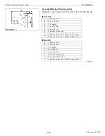
At Rated Operation
When the engine is running, the fork lever 2 (7) and
the floating lever (8) are moving with the fork lever 1 (6)
due to the tension of the governor spring (5).
During the time, the torque pin (9) is pressed into the
floating lever by centrifugal force of the governor weight
(1).
The fork lever 2 (7) comes in contact with the fuel
limitation bolt (10), and the fuel injection pump supplies
necessary fuel for rated operation.
0000004866E
(1) Flyweight
(2) Fork Lever Shaft
(3) Max. Torque Limitation
(4) Start Spring
(5) Governor Spring
(6) Fork Lever 1
(7) Fork Lever 2
(8) Floating Lever
(9) Torque Pin
(A) Fork Lever Comp
(3) Max Torque Limiter
(6) Fork Lever 1
(7) Fork Lever 2
(8) Floating Lever
(10) Fuel Limitation Bolt
KiSC issued 09, 2006 A
Содержание ZD21-EC
Страница 1: ...ZD21N EC ZD21 EC ZD28 EC WORKSHOP MANUAL ZERO TURN MOWER KiSC issued 09 2006 A ...
Страница 7: ...5 ZD21N EC ZD21 EC ZD28 EC WSM SAFETY INSTRUCTIONS KiSC issued 09 2006 A ...
Страница 8: ...6 ZD21N EC ZD21 EC ZD28 EC WSM SAFETY INSTRUCTIONS KiSC issued 09 2006 A ...
Страница 11: ...9 ZD21N EC ZD21 EC ZD28 EC WSM DIMENSIONS DIMENSIONS KiSC issued 09 2006 A ...
Страница 12: ...G GENERAL KiSC issued 09 2006 A ...
Страница 59: ...1 ENGINE KiSC issued 09 2006 A ...
Страница 60: ...CONTENTS MECHANISM 1 FUEL SYSTEM 1 M1 1 GOVERNOR 1 M1 KiSC issued 09 2006 A ...
Страница 138: ...2 TRANSAXLE KiSC issued 09 2006 A ...
Страница 178: ...3 FRONT AXLE KiSC issued 09 2006 A ...
Страница 179: ...CONTENTS MECHANISM 1 STRUCTURE 3 M1 KiSC issued 09 2006 A ...
Страница 187: ...4 HYDRAULIC SYSTEM KiSC issued 09 2006 A ...
Страница 202: ...5 ELECTRICAL SYSTEM KiSC issued 09 2006 A ...
Страница 204: ...5 M1 ZD21N EC ZD21 EC ZD28 EC WSM ELECTRICAL SYSTEM 1 WIRING DIAGRAM ZD21N ZD21 KiSC issued 09 2006 A ...
Страница 205: ...5 M2 ZD21N EC ZD21 EC ZD28 EC WSM ELECTRICAL SYSTEM ZD28 KiSC issued 09 2006 A ...
Страница 206: ...5 M3 ZD21N EC ZD21 EC ZD28 EC WSM ELECTRICAL SYSTEM ZD21N ZD21 KiSC issued 09 2006 A ...
Страница 207: ...5 M4 ZD21N EC ZD21 EC ZD28 EC WSM ELECTRICAL SYSTEM ZD28 KiSC issued 09 2006 A ...
Страница 237: ...6 ROTARY MOWER KiSC issued 09 2006 A ...
Страница 238: ...CONTENTS MECHANISM 1 POWER TRANSMISSION 6 M1 2 LIFTING MECHANISM 6 M2 KiSC issued 09 2006 A ...


