


4-S4
ZD21N-EC, ZD21-EC, ZD28-EC, WSM
HYDRAULIC SYSTEM
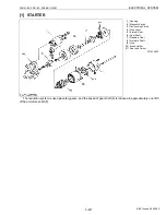
Relief Cover and Relief Valve
1. Unscrew the relief cover mounting screws (6), and remove the
relief cover (7).
2. Remove the spool return spring (9).
3. Unscrew the adjusting screw (1), and remove the adjusting shim
(2), spring (3), poppet (4) and valve seat (5).
(When reassembling)
• Replace the relief cover gasket (8) with a new one.
• Install the relief valve, noting the number of shims.
IMPORTANT
■
• After reassembling the relief valve, be sure to adjust its
setting pressure. (See page 4-S3.)
Valve Cover and Spool
1. Remove the valve cover mounting screws (5), and remove the
valve cover (6) with the control lever (8).
2. Pull out the spool (7).
3. Remove the screw (1), and remove the gasket (2), stopper spring
(3) and steel ball (4).
4. Flatten the lock washer (11), and unscrew the valve guide arm
mounting screw (12).
5. Remove the control lever (8) and valve guide arm (10).
(When reassembling)
• Visually inspect the spool for signs of scoring or damage. If
defects are found, replace it.
• Replace the valve cover gasket (14) with a new one.
• Take care not to damage the O-ring (9).
• Correctly insert the spring pin (13) of the spool (7) in the groove
of the valve guide arm (10).
W1012130
(1) Plug
(2) Adjusting Shim
(3) Spring
(4) Poppet
(5) Valve Seat
(6) Relief Cover Mounting Screw
(7) Relief Cover
(8) Relief Cover Gasket
(9) Spool Return Spring
(1) Screw
(2) Gasket
(3) Stopper Spring
(4) Steel Ball
(5) Valve Cover Mounting Screw
(6) Valve Cover
(7) Spool
(8) Control Lever
(9) O-ring
(10) Valve Guide Arm
(11) Lock Washer
(12) Valve Guide Arm Mounting Screw
(13) Spring Pin
(14) Valve Cover Gasket
KiSC issued 09, 2006 A
Содержание ZD21-EC
Страница 1: ...ZD21N EC ZD21 EC ZD28 EC WORKSHOP MANUAL ZERO TURN MOWER KiSC issued 09 2006 A ...
Страница 7: ...5 ZD21N EC ZD21 EC ZD28 EC WSM SAFETY INSTRUCTIONS KiSC issued 09 2006 A ...
Страница 8: ...6 ZD21N EC ZD21 EC ZD28 EC WSM SAFETY INSTRUCTIONS KiSC issued 09 2006 A ...
Страница 11: ...9 ZD21N EC ZD21 EC ZD28 EC WSM DIMENSIONS DIMENSIONS KiSC issued 09 2006 A ...
Страница 12: ...G GENERAL KiSC issued 09 2006 A ...
Страница 59: ...1 ENGINE KiSC issued 09 2006 A ...
Страница 60: ...CONTENTS MECHANISM 1 FUEL SYSTEM 1 M1 1 GOVERNOR 1 M1 KiSC issued 09 2006 A ...
Страница 138: ...2 TRANSAXLE KiSC issued 09 2006 A ...
Страница 178: ...3 FRONT AXLE KiSC issued 09 2006 A ...
Страница 179: ...CONTENTS MECHANISM 1 STRUCTURE 3 M1 KiSC issued 09 2006 A ...
Страница 187: ...4 HYDRAULIC SYSTEM KiSC issued 09 2006 A ...
Страница 202: ...5 ELECTRICAL SYSTEM KiSC issued 09 2006 A ...
Страница 204: ...5 M1 ZD21N EC ZD21 EC ZD28 EC WSM ELECTRICAL SYSTEM 1 WIRING DIAGRAM ZD21N ZD21 KiSC issued 09 2006 A ...
Страница 205: ...5 M2 ZD21N EC ZD21 EC ZD28 EC WSM ELECTRICAL SYSTEM ZD28 KiSC issued 09 2006 A ...
Страница 206: ...5 M3 ZD21N EC ZD21 EC ZD28 EC WSM ELECTRICAL SYSTEM ZD21N ZD21 KiSC issued 09 2006 A ...
Страница 207: ...5 M4 ZD21N EC ZD21 EC ZD28 EC WSM ELECTRICAL SYSTEM ZD28 KiSC issued 09 2006 A ...
Страница 237: ...6 ROTARY MOWER KiSC issued 09 2006 A ...
Страница 238: ...CONTENTS MECHANISM 1 POWER TRANSMISSION 6 M1 2 LIFTING MECHANISM 6 M2 KiSC issued 09 2006 A ...


