


2-S5
ZD21N-EC, ZD21-EC, ZD28-EC, WSM
TRANSAXLE
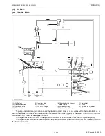
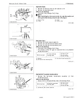
4. CHECKING AND ADJUSTING
Checking Neutral
1. Park machine safely.
2. Set the motion control levers are in the NEUTRAL position.
3. Move the PTO lever to OFF position and apply the parking brake.
4. With the operator on the seat and start the engine.
5. Move the throttle lever to Max. speed position.
6. Release the parking brake.
7. Check the drive wheels, the wheels should not move.
8. If movements is noted, perform adjustment as follows.
W1013323
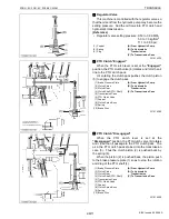
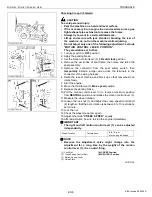
Adjusting Neutral
CAUTION
To avoid personal injury:
• Park the machine on a hard and level surface.
• If it is necessary to run engine in an enclosed area, use a gas
tight exhaust pipe extension to remove the fumes.
• Always try to work in a well-ventilated area.
• Lift up and secure with jack stands or blocking the rear of
the machine, do not run the machine while adjusting.
• Do not adjust only one of the following adjustment; exclude
“MOTION CONTROL LEVER POSITION”.
They are relative each other.
1. Turn key switch to OFF position.
2. Apply the parking brake.
3. Set the motion control levers (2) to Neutral lock position.
4. Remove the set knobs of seat frame, then raise and latch the
seat assembly.
5. Remove the connector from the seat safety switch, then
temporarily install a jumper wire across the terminals in the
connector of the wiring harness.
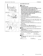
6. Raise the rear of machine and block up so that rear wheel can
rotate freely.
7. Loosen the lock nuts from the ball joints on the two rods.
8. Start the engine.
9. Move the throttle lever to Max. speed position.
10.Release the parking brake.
11.Adjust the speed control rod (3) length by rotating the double nuts
on the rod appropriate direction until the rear wheel no rotation
from reverse rotation.
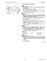
12.The left rod assembly controls left wheel and the right rod
assembly controls right wheel.
13.Repeat on opposite side of unit, tighten lock nuts (4) securely
against ball joint.
14.Shut off the machine. Remove jumper wire from wire harness
connector and plug connector or into seat safety switch.
IMPORTANT
■
• The right and left motion control lever (2) can be adjusted
independently.
• This machine has a creep speed.
W1013453
(1) Guide Plate
(2) Motion Control Lever
(3) Speed Control Rod
(4) Lock Nut
KiSC issued 09, 2006 A
Содержание ZD21-EC
Страница 1: ...ZD21N EC ZD21 EC ZD28 EC WORKSHOP MANUAL ZERO TURN MOWER KiSC issued 09 2006 A ...
Страница 7: ...5 ZD21N EC ZD21 EC ZD28 EC WSM SAFETY INSTRUCTIONS KiSC issued 09 2006 A ...
Страница 8: ...6 ZD21N EC ZD21 EC ZD28 EC WSM SAFETY INSTRUCTIONS KiSC issued 09 2006 A ...
Страница 11: ...9 ZD21N EC ZD21 EC ZD28 EC WSM DIMENSIONS DIMENSIONS KiSC issued 09 2006 A ...
Страница 12: ...G GENERAL KiSC issued 09 2006 A ...
Страница 59: ...1 ENGINE KiSC issued 09 2006 A ...
Страница 60: ...CONTENTS MECHANISM 1 FUEL SYSTEM 1 M1 1 GOVERNOR 1 M1 KiSC issued 09 2006 A ...
Страница 138: ...2 TRANSAXLE KiSC issued 09 2006 A ...
Страница 178: ...3 FRONT AXLE KiSC issued 09 2006 A ...
Страница 179: ...CONTENTS MECHANISM 1 STRUCTURE 3 M1 KiSC issued 09 2006 A ...
Страница 187: ...4 HYDRAULIC SYSTEM KiSC issued 09 2006 A ...
Страница 202: ...5 ELECTRICAL SYSTEM KiSC issued 09 2006 A ...
Страница 204: ...5 M1 ZD21N EC ZD21 EC ZD28 EC WSM ELECTRICAL SYSTEM 1 WIRING DIAGRAM ZD21N ZD21 KiSC issued 09 2006 A ...
Страница 205: ...5 M2 ZD21N EC ZD21 EC ZD28 EC WSM ELECTRICAL SYSTEM ZD28 KiSC issued 09 2006 A ...
Страница 206: ...5 M3 ZD21N EC ZD21 EC ZD28 EC WSM ELECTRICAL SYSTEM ZD21N ZD21 KiSC issued 09 2006 A ...
Страница 207: ...5 M4 ZD21N EC ZD21 EC ZD28 EC WSM ELECTRICAL SYSTEM ZD28 KiSC issued 09 2006 A ...
Страница 237: ...6 ROTARY MOWER KiSC issued 09 2006 A ...
Страница 238: ...CONTENTS MECHANISM 1 POWER TRANSMISSION 6 M1 2 LIFTING MECHANISM 6 M2 KiSC issued 09 2006 A ...


