


2-M4
ZD21N-EC, ZD21-EC, ZD28-EC, WSM
TRANSAXLE
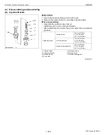
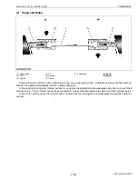
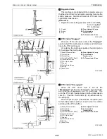
(3) Check Valve and High Pressure Relief Valve
The check and high-pressure relief valve consists of
pressure poppet (2), check valve seat (1), relief valve
spring (3), spring guide (4) and check valve spring (5).
The valve is used to prevent an overload that would
happen at a quick start, sudden stop or even during usual
running. This valve doubles as a check valve.
The check and high-pressure relief valves are laid out
facing each other as shown in the figure.
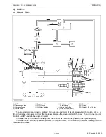
In neutral, both valves are open and charging oil
enters into the main oil circuit through the valves. (A)
At normal operation, the check valve in the high-
pressure side is closed and it pushes and opens the
another one. An excessive charge flow goes through the
charge relief valve into HST housing. (B)
The check and high-pressure relief valve along the
high-pressure line serves as a high-pressure relief valve.
If the pressure exceeds a high-pressure limit level, the
pressure poppet opens itself against the relief valve
spring (3) force and opens the valve seat that is located
between the check valve seat (1) and the pressure
poppet (2). Now the flow goes from P1 to P2 and P3. (C)
If the P1 pressure drops, the relief valve spring forces
the valve seat closed against the pressure. The high-
pressure oil at P1 does not flow to P2 any longer.
As discussed above, the check and high-pressure
relief valve protects engines, pumps, motors, gears and
even the machine itself from overload.
W1012950
3GZAAADKP004A
(1)
(2) (3)
(4) (5)
(6)
P3
P2
P1
P3
P2
P1
P3
P2
P1
(A)
(B)
(C)
Oil temperature
Valve operating pressure
50 °C (122 °F)
26.3 to 29.6 MPa
290 to 300 kgf/cm
2
4125 to 4267 psi
(1) Check Valve Seat
(2) Pressure Poppet
(3) Relief Valve Spring
(4) Spring Guide
(5) Check Valve Spring
(6) Valve Plug
(A) In Neutral (Stop)
(B) When Check Valve
Activating (Normal
Operation)
(C) When High Pressure Relief
Valve Activating
KiSC issued 09, 2006 A
Содержание ZD21-EC
Страница 1: ...ZD21N EC ZD21 EC ZD28 EC WORKSHOP MANUAL ZERO TURN MOWER KiSC issued 09 2006 A ...
Страница 7: ...5 ZD21N EC ZD21 EC ZD28 EC WSM SAFETY INSTRUCTIONS KiSC issued 09 2006 A ...
Страница 8: ...6 ZD21N EC ZD21 EC ZD28 EC WSM SAFETY INSTRUCTIONS KiSC issued 09 2006 A ...
Страница 11: ...9 ZD21N EC ZD21 EC ZD28 EC WSM DIMENSIONS DIMENSIONS KiSC issued 09 2006 A ...
Страница 12: ...G GENERAL KiSC issued 09 2006 A ...
Страница 59: ...1 ENGINE KiSC issued 09 2006 A ...
Страница 60: ...CONTENTS MECHANISM 1 FUEL SYSTEM 1 M1 1 GOVERNOR 1 M1 KiSC issued 09 2006 A ...
Страница 138: ...2 TRANSAXLE KiSC issued 09 2006 A ...
Страница 178: ...3 FRONT AXLE KiSC issued 09 2006 A ...
Страница 179: ...CONTENTS MECHANISM 1 STRUCTURE 3 M1 KiSC issued 09 2006 A ...
Страница 187: ...4 HYDRAULIC SYSTEM KiSC issued 09 2006 A ...
Страница 202: ...5 ELECTRICAL SYSTEM KiSC issued 09 2006 A ...
Страница 204: ...5 M1 ZD21N EC ZD21 EC ZD28 EC WSM ELECTRICAL SYSTEM 1 WIRING DIAGRAM ZD21N ZD21 KiSC issued 09 2006 A ...
Страница 205: ...5 M2 ZD21N EC ZD21 EC ZD28 EC WSM ELECTRICAL SYSTEM ZD28 KiSC issued 09 2006 A ...
Страница 206: ...5 M3 ZD21N EC ZD21 EC ZD28 EC WSM ELECTRICAL SYSTEM ZD21N ZD21 KiSC issued 09 2006 A ...
Страница 207: ...5 M4 ZD21N EC ZD21 EC ZD28 EC WSM ELECTRICAL SYSTEM ZD28 KiSC issued 09 2006 A ...
Страница 237: ...6 ROTARY MOWER KiSC issued 09 2006 A ...
Страница 238: ...CONTENTS MECHANISM 1 POWER TRANSMISSION 6 M1 2 LIFTING MECHANISM 6 M2 KiSC issued 09 2006 A ...


