Solar controller
SOL3-1
Installation and operatingmanual
Firmware version 1.0x, November 2008
Страница 1: ...Solar controller SOL3 1 Installation and operating manual Firmware version 1 0x November 2008 ...
Страница 2: ...r other financial losses are excluded This does not apply if the damage caused by intent or gross negligence In case of negligent violations of major contractual obligations our liability is limited to the foreseeable damage Security advices Only qualified personnel that is familiar with installation and commissioning of this product is allowed to mount the device and put it into operation Appropr...
Страница 3: ...eset to Factory default settings 16 3 Manual operating mode 17 4 Solar circuit functions 18 4 1 System diagram 18 4 1 1 Basic control functions 18 4 1 2 Limiting the storage temperature 20 4 1 3 Overheating protection 20 4 1 4 Collector minimum temperature 21 4 1 5 Start up function 21 4 1 6 Forced pump operation anti locked 22 4 1 7 Collector Antifreeze 22 5 System wide functions 23 5 1 Automatic...
Страница 4: ...Bus Gateway 33 7 6 Description of the adjustable communication settings 33 7 7 Memory module 34 7 8 55Viewer for visualization and remote maintenance 35 7 9 Data Logging 36 8 Mounting 37 9 Electrical connection 39 9 1 Wiring diagram 40 10 Appendix 41 10 1 Function block lists 41 10 2 Parameter lists 42 10 3 Resistance values 46 10 4 Technical specifications 47 10 5 Accessories 48 10 6 Customer dat...
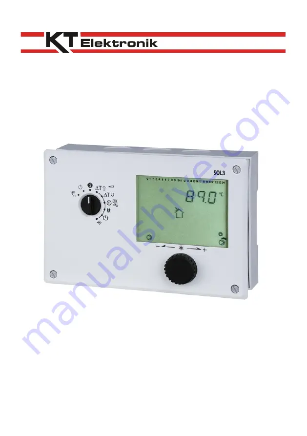
Страница 5: ...he current date and time have to be set at initial operation of the controller Chapter 1 5 1 1 Controls The operational controls are located on the front side of the controller 1 1 1 Control Button and selector switch Control button Turn Display select settings and function blocks Push confirm selection or setting EB_37381_SOL3 1_EN002 5 ...
Страница 6: ...ng mode Information level display operating behaviour of system Turning off the control functions Controller remains in operation Manual operating mode manual pump control Rotary switch Settings Solar Turn on threshold Solar Turn off threshold Usage schedules1 for heating and hot water Party mode1 System time Setting time date and year Configuration and settings level 1 not available for SOL3 1 6 ...
Страница 7: ... operation chapter 3 1 3 Display During operation the display shows the current time as well as informations about the status of the controller Symbols mark the operational status of the controller Current time display Malfunction Antifreeze Solar circuit Manual operating mode Stand by OM Collector pump CP The controller status can be viewed at operating mode level Chapter 1 4 EB_37381_SOL3 1_EN00...
Страница 8: ...h position Information level one can retrieve informations about time date as well as the temperature set points for the connected sensors and their current temperature Procedure Select value The screen now displays different items one after the other depending on the configuration of the controller __ __ Current time Collector temperature CF Temperature at storage sensor SF Display the operating ...
Страница 9: ...ary switch to the position system time right hand Display shows current time setting Change the time setting Confirm the time set Display shows current year setting Change the year setting Confirm the year set Display show current date setting day month Change date setting Confirm the date set Display shows current time setting Move the rotary switch back to the Information level position left han...
Страница 10: ...equentially displayed Controller ID Memory usage Data logging module chapter 7 9 Modbus client address Operating hours of solar circuit Start of solar circuit Access advanced operation level Switch to configuration and settings level Display shows 0 0 0 0 Enter access code 1999 Confirm code Display shows 0 0 0 0 Move the rotary switch back to the Information level position left hand 10 EB_37381_SO...
Страница 11: ...or at least has to be higher than the storage temperature in order to keep the pump running once it has been turned on Switch position Setting FS Value range Turn on threshold 8 K 1 to 50 K Switch position Setting FS Value range Turn off threshold 4 K 1 to 50 K Procedure Move rotary switch to the position turn on threshold or turn off threshold Change temperature Move the rotary switch back to the...
Страница 12: ...trization described in this chapter can only be performed by entering a valid controller access code The access code provided by the factory for first time use can be found in the appendix To avoid an unauthorized use it is recommended to cut out or black out the code Additionally the standard code can be replaced by an individual one Chapter 5 4 12 EB_37381_SOL3 1_EN002 Information level Figure 1...
Страница 13: ...d access code Confirm code Display PA3 Select configuration level Access configuration level Select function block Activated function blocks are marked with 1 Deactivated function blocks are marked with 0 Switch to edit mode F__ flashes Activate function block Display F__ 1 An active function block can be identified by a black square that is displayed right hand below the function block number at ...
Страница 14: ...n the Appendix will be accessible Chapter The functions are grouped by topic PA3 Solar circuit PA5 General PA6 Modbus Communication Procedure Switch to configuration and settings level Display shows 0 0 0 0 Enter a valid access code Confirm code Display PA3 Select settings level Access settings level Select parameter Switch to edit mode Edit parameter Confirm parameter To set more parameters repea...
Страница 15: ...nt can be deleted by setting 0 in F20 Procedure Switch to configuration and settings level Display shows 0 0 0 0 Enter a valid access code Confirm code Display PA3 Select configuration level CO5 Access configuration level CO5 Select function block F20 Switch to edit mode Select sensor icon Temperature at solar collector CF Temperature at storage sensor SF Display measured value Value flashes Corre...
Страница 16: ... the parameters set in level PA3 and PA5 can be reset to factory default settings Procedure Switch to configuration and settings level Enter access code 1991 Confirm code 16 EB_37381_SOL3 1_EN002 Note The error message Err 2 will be generated while resetting to the factory default settings It will be removed automatically shortly after midnight ...
Страница 17: ...ump and other units Confirm editing The changed values remain as long as the manual operating mode stays active Move the rotary switch back to the Information level position left hand The manual operating mode of the affected control circuit can be deactivated by selecting any other operating mode EB_37381_SOL3 1_EN002 17 Note Just by moving the rotary switch to the position manual operating mode ...
Страница 18: ...d one storage tank 4 1 1 Basic control functions The controller monitors the collector temperature sensor CF as well as the storage temperature sensor SF and turns the collector pump CP on once enough solar energy is available to heat up the storage tank The temperature chart shows how regulation works under consideration of the parameters 18 EB_37381_SOL3 1_EN002 Figure 2 System diagram ...
Страница 19: ...pump is turned on as soon as the minimum idle time elapses D The collector temperature dropped and falls below the turn off threshold again SF 4 K The collector pump is turned off E The collector temperature exceeds the storage temperature by more than the turn on gap 8 K The collector pump is turned on F The collector temperature quickly dropped below the turn off threshold again The pump remains...
Страница 20: ... additional components such as mixer taps and therefore is no risk higher storage temperatures can and should be allowed Setting FS Parameter level Value range Maximum storage temperature turn off condition 60 C PA3 50 to 160 C Maximum storage temperature turn on condition 58 C PA3 50 to 160 C 4 1 3 Overheating protection If the collector temperature exceed this maximum value default factory setti...
Страница 21: ... flat plate collectors where temperature measurement does not work well once the circulation is suspended The temperature at the collector sensor only slowly increases even if the collector is illuminated by the sun The start up function can be activated for these cases This function can only be used if the collector temperature is below the turn on threshold but above the collector minimum temper...
Страница 22: ...pump in order to prevent a freezing of the collector Operation The collector pump is turned on if the temperature at the collector sensor drops below 5 C At 6 C it turns off again but running for the minimum running time set The following icon additionally appears if the pump is turned on because for means of antifreeze Functions FS Configuration Collector antifreeze 0 CO3 F02 1 22 EB_37381_SOL3 1...
Страница 23: ...used to lock the manual operating mode in order to protect the system When activated the system is run in automatic mode when the rotary switch is positioned at Functions FS Configuration Locking manual operating mode 0 CO5 F21 1 5 3 Locking the rotary switch When activated the system is run in automatic mode regardless of the rotary switch position No further settings can be programmed using the ...
Страница 24: ...The individual code can be selected from 0100 to 1900 Procedure Switch to configuration and settings level Display shows 0 0 0 0 Enter access code 1995 Confirm code Enter a valid access code Confirm code Code flashes Enter individual code Confirm entered code The new valid code is from now on the one confirmed Move the rotary switch back to the Information level position left hand 24 EB_37381_SOL3...
Страница 25: ...temperature monitoring alarm chapter 6 3 Err 7 unauthorized access captured chapter 6 3 6 2 Sensor failure According to the error list sensor failures are indicated by the message Err 1 at error level Detailed informations can be retrieved at information level by querying the temperature values Each sensor icon combined with three small horizontal bars instead of a temperature value indicate a fau...
Страница 26: ...ng mode with error reporting function each change of error status error detection error correction triggers a dial up connection to the building master control system station BCS to report the status change The errors that should affect the error status register can be set after having entered the access code 0025 The default factory setting 465 causes that only the error messages in bold in the f...
Страница 27: ...for the programmed number of times The providers SMS service numbers TAPnr in Germany at the time of writing are D1 49 171 2521002 49 171 2521099 alternatively available E Plus 49 177 1167 Cellnet UK 44 786 098 0480 mobile comm network of D1 D2 and E Plus 0 respectively the pre dial number has to be prepended in telephone installations with secondary structure The subscriber number HAndi has to be...
Страница 28: ...ommunication module KOM232M An automatic communication is basically only initiated in case of failures The controller operates in an autonomous way but can be contacted read out and adjusted at any time via modem 2 wire bus operation with communication module iCon485 RS 232 connection operation with communication module KOM232PC Figure 4 Modem Bus connection 1 optional communication module KOM232P...
Страница 29: ...on485 requires a permanent bus connection data cable Each controller and control unit is wired to an open token ring The end of the wire is connected to the master control system via an RS 485 RS 232 converter e g CoRe01 The bus connection range cable length is limited to a maximum of 1200 m A maximum of 126 devices can be connected to such a segment In segments with a longer distance 1200m or in ...
Страница 30: ...ction and over voltage voltage surge protection have to be attended to Functions FS Configuration Modbus 1 CO6 F01 1 Modbus with 16 bit addressing 0 CO6 F02 1 Modem function 0 CO6 F03 1 Automatic modem configuration 0 CO6 F04 1 Blocking the BCS dial up 0 CO6 F05 BCS dial up on corrected failures 0 CO6 F06 Control system monitoring 0 CO6 F07 0 Setting FS Parameter level Value range Station address ...
Страница 31: ...livery are triggered Bit D6 is deleted as soon as the error status register is read out by the control system and the connection is terminated The function modem dial up blocking can be selected in special cases in order to suppress dial ups to report failures With the function modem dial up on corrected failures the BCS is additionally informed if a previously reported failure no longer exists By...
Страница 32: ...KOM232M 7 4 Data Modem DataMod11 The connector for the optional data modem DataMod11 Mat No 11991 is located on the left side front panel view inside the controller housing RJ45 connector Settings and notes from chapter 7 3 remain valid Wiring diagram for DataMod11 32 EB_37381_SOL3 1_EN002 ...
Страница 33: ...eters into building control systems of HVAC system networks The ModBus MBus Gateway allows an easy to handle connection of heat electricity or water flow meters Up to 6 meter according to EN 1434 3 can be connected Settings and notes from chapter 7 2 remain valid Wiring diagram for ModBus MBus Gateway 7 6 Description of the adjustable communication settings Station address ST This address is used ...
Страница 34: ...trol system including area code if needed has to be entered here Short dialling breaks can be provided by entering a P where each P equals 1 second the end of the dialling string has to be indicated by entering The phone number can be up to 22 characters long Example phone number 069 2 seconds break 4009 1 second break 0 0 6 9 P P 4 0 0 9 P 0 11 characters 7 7 Memory module The memory module part ...
Страница 35: ...ll controller settings and data programmed schedules and heat meter data 55Viewer also allows to modify controller parameters A personal computer with the following minimum requirements is needed PC with a Pentium II processor or equivalent CPU 300 MHz or higher 500 MHz or more are recommended Serial port respectively an appropriate modem for dial up connections SVGA graphics card min resolution 8...
Страница 36: ...e current memory capacity can be viewed in the advanced information level it is the second value displayed range 0 to 6035 in menu item Info 2 After plugging in the data logging module the value is not displayed before the first scanning cycle is complete The saving cycle interval in minutes range from 1 to 99 minutes can be programmed after entering the access code 0010 The default factory settin...
Страница 37: ...cording to chapter 9 7 Remount housing 8 Tighten both screws 1 Wall mounting 1 Loose both screws 1 2 Separate housing and mounting panel 3 Eventually drill holes at the predefined positions with the given dimensions Fix mounting panel with 4 screws 4 Perform electrical connection according to chapter 9 5 Remount housing 6 Tighten both screws 1 DIN rail mounting 1 Hook the spring loaded hooks 4 to ...
Страница 38: ...Installation and operating manual KT Elektronik 38 EB_37381_SOL3 1_EN002 Figure 5 Mounting ...
Страница 39: ...th conductor PE with the shortest possible cable 10 mm in diameter Inductances in the cabinet like contactor coils are to be supplied with appropriate snubber circuits RC snubber High field strength cabinet components like transformers and frequency inverters should be shielded by separating plates with good earthing Surge Protection Measures Signal lines routed outdoor or over long distances shou...
Страница 40: ...nd for the connection diagrams CF Collector sensor SF Storage sensor CP Collector pump 9 1 Wiring diagram 40 EB_37381_SOL3 1_EN002 Figure 6 Terminal assignment 21 20 19 18 N L1 Ansicht auf Sockel View of termina l base Vue sur le socle de l a rmoire SOL3 1 Vor Eingriff N etz a us Power off before intervention Couper I alimentation avant toute intervention 12 11 10 SF CF Fühler COM CP ...
Страница 41: ...lizes CO5 F00 1 any access to return flow volume flow rate and performance settings is locked F Function FS Function block parameter description value range factory default setting 01 02 03 Sensor initialization 1 0 0 Pt 1000 08 Summer time Winter time switching 1 19 Temperature monitoring 0 CO5 F19 1 Temperature monitoring active 20 Sensor calibration 1 CO5 F20 1 Setting all sensor calibration va...
Страница 42: ... on failure only with CO6 F03 1 06 BCS dial up on corrected failures 0 all CO6 F06 1 additional dial up on corrected failures only with CO6 F03 1 07 Control system monitoring all CO6 F07 1 Reset all collective level bits to autonomous on missing connection only with CO6 F01 1 08 SMS CO6 F08 1 SMS delivery active F Function block number FS factory setting Sys System variant ID 10 2 Parameter lists ...
Страница 43: ...0 C START C Maximum allowed storage tank temperature turn on value 50 to 160 C 58 C STOP C Maximum allowed collector temperature turn off value 90 to 160 C 130 C START C Maximum allowed collector temperature turn on value 90 to 160 C 110 C STOP C Minimum allowed collector temperature turn off value 20 to 50 C 30 C EB_37381_SOL3 1_EN002 43 ...
Страница 44: ...TART C Minimum allowed collector temperature turn on value 20 to 50 C 35 C PA6 Modbus parameter Symbol Icon Parameter name Value range Modbus client address 1 to 247 255 with CO6 F02 1 valid 1 bis 32000 Modem dialling pause P 0 to 255 min 5 min Modem time out T 1 to 255 min 5 min 44 EB_37381_SOL3 1_EN002 ...
Страница 45: ... C 0 to 255 15 Phone number of the BCS TELnr max 22 digits 1 2 3 9 0 End of string P Pause SMS service numbers TAPnr max 22 digits 1 2 3 9 0 End of string P Pause Subscriber number Cell phone number HAndi max 22 digits 1 2 3 9 0 End of string P Pause EB_37381_SOL3 1_EN002 45 ...
Страница 46: ...t sensor Temperature Resistance value with Pt1000 sensor 40 C 842 7 Ω 30 C 882 0 Ω 20 C 921 6 Ω 10 C 960 9 Ω 0 C 1000 0 Ω 10 C 1039 0 Ω 20 C 1077 9 Ω 30 C 1116 7 Ω 40 C 1155 4 Ω 50 C 1194 0 Ω 60 C 1232 4 Ω 70 C 1270 7 Ω 80 C 1308 9 Ω 90 C 1347 0 Ω 100 C 1385 0 Ω 110 C 1422 9 Ω 120 C 1441 7 Ω 130 C 1499 4 Ω 140 C 1535 8 Ω 150 C 1573 1 Ω 160 C 1610 4 Ω 46 EB_37381_SOL3 1_EN002 ...
Страница 47: ...ctor 1 x Interface for data logging module 1 x Interface for memory module Operating voltage 85 bis 250 V 48 bis 62 Hz max 1 5 W Ambient temperature 0 to 40 C operating 10 to 60 C storage and shipping Type of protection IP 40 according to IEC 529 Protection class II according to VDE 0106 Pollution degree 2 according to VDE 0110 Overvoltage category II according to VDE 0110 Humidity class F accordi...
Страница 48: ...ter Repeater for RS232 or RS485 interfaces 11998 SA5000 RS485 Surge protection 11995 USB CO3 RS485 to USB converter 3 Software Datalogging Viewer included 37699 DataMem Data logging module to capture controller data directly connected to the controller 17090 ParaMem Parameter saving module for controller parameter transfer 37160 55Viewer Remote control software 55Viewer 11997 MBus ModBus MBus ModB...
Страница 49: ...SOL3 1 Function block settings in configuration levels CO1 CO2 CO3 CO5 CO6 F01 F02 F03 F04 F05 F06 F07 F08 F09 F10 F11 F12 F13 F14 F15 F16 F17 F18 F19 F20 F21 F22 F23 EB_37381_SOL3 1_EN002 49 ...
Страница 50: ...rn off condition 90 to 160 C Maximum collector temperature turn on condition 90 to 160 C minimum collector temperature turn off condition 20 to 50 C minimum collector temperature turn on condition 20 to 50 C PA6 Modbus parameter Setting PA6 Value range Station address ST 1 to 247 1 to 32000 Modem dialling pause P 0 to 255 min Modem time out T 1 to 255 min Number of dial attempts C 1 to 255 Phone n...
Страница 51: ...rameter level Rk Control circuit t time T Temperature FS Default factory setting COM Common ground 10 8 Access codes 1732 General parameter setting and configuration factory setting 1999 Locking unlocking the extended information level 1995 Changing the access code for parameter setting and configuration 1991 Load default factory settings 0025 Changing error display FSR 0010 Changing data logging ...
Страница 52: ...KT Elektronik GmbH Berlinickestrasse 11 12165 Berlin Germany Telephone 49 30 790805 0 Telefax 49 30 790805 20 E mail info kt elektronik de Internet www kt elektronik de EB_37381_SOL3 1_EN002 06 2010 ...