21
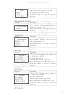
8.1.12 Temperature
8.1.13 Status information
8.1.14 Error information
Interface
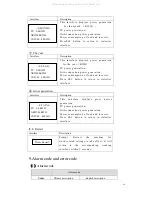
8.1.15 System setting
Interface Description
Interface
Interface
Interface
Description
S y s te m i n f o r m a ti o n
:
Power-up mode,
standby mode, hybrid grid-connection,
off-grid operation, mains charging mode, PV
charging mode, bypass mode, fault mode,
DSP programming, ARM programming
INV: standby mode, off-grid inverter mode,
grid-connected mode, and transition of grid-connection
to off-grid, transition of off-grid to grid mode
DCDC: standby mode, soft start mode, charging mode,
discharging mode
POWER
PV I/P
:
W
LOAD
:
W
BAT
:
W
PV real-time total power
BACKUP real-time load
Battery real-time load
(
+ means discharge, -
means charge
)
Real-time temperature of inverter system radiator
Real-time temperature ofBidirectional DCDC
System Radiator
Internal temperature of chassis
TEMPERATURE
INVER
:
25
℃
DCDC
:
26
℃
INSIDE
:
27
℃
SATE
SYS
:
ERROR
INV
:
STANDBY
DCDC
:
STANDBY
Alarm code
(
see Chapter 9
)
Error code
(
see Chapter 9
)
ERROR NO.
WARNING
:
W11-1
FAULT
:
F10-1
All manuals and user guides at all-guides.com


