background image


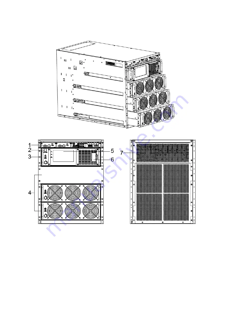
  3.2.2 Sub Rack UPS 

60kVA&80kVA&100kVA (N+1, without breaker) 


                Front View                                                                        Rear View 


Содержание HPM3300E

Страница 1: ...ut high frequency online UPS designed by our R D team who is with years of designing experiences on UPS With excellent electrical performance perfect intelligent monitoring and network functions smart appearance complying with EMC and safety standards The UPS meets the world s advanced level Read this manual carefully before installation This manual provides technical support to the operator of th...

Страница 2: ... Installation 28 3 11 1 Cabinet installation 28 3 11 2 Parallel cable installation 29 3 12 LBS installation optional 30 3 12 1 LCD setting 30 3 12 2 LBS cable installation 30 3 12 3 UPS installation 31 4 Operation 31 4 1 Operation Modes 31 4 2 Turn on off UPS 34 4 2 1 Restart procedure 34 4 2 2 Test procedure 34 4 2 3 Cold start procedure 34 4 2 4 MAINTENANCE BYPASS 35 4 2 5 Shut down procedure 35...

Страница 3: ... spilled from the battery is strongly poisonous and do harmful to body 4 Please avoid short circuit between anode and cathode of battery otherwise it will cause spark or fire 5 Don t disassemble the UPS cover or there may be an electric shock 6 Check if there exists high voltage before touching the battery 7 Working environment and storage way will affect the lifetime and reliability of the UPS Av...

Страница 4: ...grated solution for data center Digital control Modularized design High power density design The height of the single module is 3U N X parallel redundancy This series UPS adopts N X parallel redundancy design user can set different redundancy according to the importance of the load While the redundancy modules are set more than two the availability of UPS system will achieve 99 999 which may satis...

Страница 5: ...alized monitoring module is also available EPO and REPO function 3 Installation 3 1 Unpack checking 1 Don t lean the UPS when moving it out from the packaging 2 Check the appearance to see if the UPS is damaged or not during the transportation do not switch on the UPS if any damage found Please contact the dealer right away 3 Check the accessories according to the packing list and contact the deal...

Страница 6: ...5 Front View Rear View 60kVA 80kVA 100kVA N 1 with Maintenance breaker Front View Rear View ...

Страница 7: ...6 60kVA 80kVA 100kVA N 1 with full breakers Front View Rear View 90kVA 120kVA 150kVA without breaker Front View Rear View ...

Страница 8: ...7 90kVA 120kVA 150kVA with Maintenance breaker Front View Rear View 90kVA 120kVA 150kVA with full breakers Front View Rear View ...

Страница 9: ...8 3 2 2 Sub Rack UPS 60kVA 80kVA 100kVA N 1 without breaker Front View Rear View ...

Страница 10: ...9 60kVA 80kVA 100kVA N 1 with Maintenance breaker Front View Rear View 60kVA 80kVA 100kVA N 1 with full breakers Front View Rear View ...

Страница 11: ...10 90kVA 120kVA 150kVA without breaker Front View Rear View 90kVA 120kVA 150kVA with Maintenance breaker Front View Rear View ...

Страница 12: ...module 5 LCD panel Display UPS data and status 6 Intelligent Slot SNMP card Relay card 7 Terminal block cover 8 Wheels for standalone UPS 9 Left cabinet cover for standalone UPS 10 Right cabinet cover for standalone UPS 11 Distribution module Control unit 1 ECU1 2 Centralized control unit 2 Dry contact unit 3 monitor unit ...

Страница 13: ...al port BAT 0V battery breaker auxiliary contact singnal port 3 The other port BTG 0V battery grounding detect singnal input port DRV 0V battery breaker driver singnal output port SPD 0V SPD detect singnal input port GEN 0V generator detect singnal input port 4 BP_FEEDBACK PIN1_NC PIN2_NO PIN4_common 5 Optional dry contacts 6 ports can optional by LCD Monitor unit 1 BAT_T NTC temperature sensor po...

Страница 14: ...S485 Distribution module 1 Mains breaker 2 Bypass breaker 3 Maintenance breaker and it s cover 4 Output breaker 5 AUX MAINT Maintenance breaker auxiliary contacts port connect to UPS MAINTAIN AUXSWS port for detect maintenance breaker status Normally closed 6 AUX OUTPUT Output breaker auxiliary contacts port connect to UPS OUTPUT AUXSWS port for detect output breaker status Normally closed ...

Страница 15: ...connect to PDU AUX MAINT port for detect maintenance breaker status 2 OUTPUT AUXSWS Output breaker auxiliary contacts port connect to PDU OUTPUT AUX OUTPUT port for detect output breaker status 3 3 UPS module appearance Front View Side View 1 Module fixed screw 2 LED ...

Страница 16: ...15 3 Module switch 4 Fan 3 4 Installation 3 4 1 Standalone UPS change to sub rack UPS 3 4 1 1 Remove the screws M5 36PCS to remove the modules panel and casters ...

Страница 17: ...16 3 4 1 2 Remove the screws M4 18PCS of the front side and rear side to remove the right and left covers ...

Страница 18: ...sub rack UPS into standard 19 cabinet and screw the cabinet screws M5 12 to fix the cabinet control module and bypass module CAUTION Bypass module Module_IN 1 switch must be at OFF status before put into cabinet and then switch to ON status after put into cabinet ...

Страница 19: ... Module_IN 1 switch must be at OFF status before put into cabinet and then switch to ON status after put into cabinet 3 5 Installation notes Note Consider for the convenience of operation and maintenance the space in front and back of the cabinet should be left at least 800mm and 800mm respectively when installing the cabinet ...

Страница 20: ...n danger of electric shock Batteries should be mounted in an environment where the temperature is within the required specs Temperature is a major factor in determining battery life and capacity In a normal installation the battery temperature is maintained between 15 C and 25 C Keep batteries away from heat sources or main air ventilation area etc WARNING Typical battery performance data are quot...

Страница 21: ...ker or a set of fuses located close to the battery UPS Output Any external distribution board used for load distribution shall be fitted with protective devices that may avoid the risk of UPS overloaded Over current Protection device shall be installed at the distribution panel of the incoming main supply It may identify the power cables current capacity as well as the overload capacity of the sys...

Страница 22: ...by default and compatible with application scenarios with 30 50 batteries When the mains input and bypass input share a power source configure both types of input power cables as mains input power cables The cables listed in Table are used only when the following requirements are met Routing mode Routing the cables over the cable ladder or bracket in a single layer IEC60364 5 52 middle E The ambie...

Страница 23: ...m Bypass input connector Crimped OT terminals M10 11mm 26N m Battery input connector Crimped OT terminals M10 11mm 26N m Output connector Crimped OT terminals M10 11mm 26N m Grounding connector Crimped OT terminals M10 11mm 26N m 3 7 3 Recommended input front end and output back end circuit breakers UPS capacity Component Specifications 80k Mains input breaker 160A 3P Bypass input breaker 160A 3P ...

Страница 24: ...CK AND FIRE 3 8 Power cable connect Once the equipment has been finally positioned and secured connect the power cables as described in the following procedure Verify the UPS is totally isolated from its external power source and also all power isolators of the UPS are open Check to see if they are electrically isolated and post any necessary warning signs to prevent their inadvertent operation Op...

Страница 25: ...put Phase L2 Vout L3 Output Phase L3 Vin L3 Primary input Phase L3 Vout N Output Neutral Vin N Input Neutral for primary and secondary input PE Grounding BAT Positive terminal of the batteries string BATN Neutral terminal of the batteries string BAT Negative terminal of the batteries string 3 8 2 Dual input connection 60kVA 90kVA ...

Страница 26: ...ss input line optional Vout L1 Output Phase L1 Vin L1 Primary input Phase L1 Vout L2 Output Phase L2 Vin L2 Primary input Phase L2 Vout L3 Output Phase L3 Vin L3 Primary input Phase L3 Vout N Output Neutral Vin N Input Neutral for primary and secondary input PE Grounding ...

Страница 27: ...low the power connections All cabinets in the UPS must be grounded properly CAUTION The earthing and neutral bonding arrangement must be in accordance with local and national codes of practice 3 9 Battery connection The UPS adopts positive and negative double battery framework total 30 optional 32 34 36 38 40 42 44 46 48 50 in series A neutral cable is retrieved from the joint between the cathode ...

Страница 28: ...connection i e inter tier and inter block connections are from to terminals Don t mix batteries with different capacity or different brands or even mix up new and old batteries either WARNING Ensure correct polarity of string end connections to the Battery Circuit Breaker and from the Battery Circuit Breaker to the UPS terminals i e to to but disconnect one or more battery cell links in each tier ...

Страница 29: ...ill light and green indicator flash Remove the screws 1 of the module and remove the module from the cabinet WARNING 1 Before start the module the module_ON switch must on the ON status and the red indicator must flash or off 2 Before remove the module the module_ON switch must on the OFF status and the red indicator must light 3 When insert the module under battery mode please press ON button at ...

Страница 30: ...l UPS must be the same rated and connected to the same way bypass power supply Bypass and the mains input power must be received with the same neutral The output of all UPS machines must be connected to a common output bus All bypass input cables and UPS output cables should be of the same length and specification which is to make the machine operate in the bypass mode and compare the current shar...

Страница 31: ...D setting Set every UPS of the systems to be LBS Master or LBS Slave For instance if the UPS belongs to LBS master system its LBS setting must be set to Master 3 12 2 LBS cable installation The two ports of one mesh wire should be plug into RJ45 interface of any one UPS of both master and slave system ...

Страница 32: ...e conversion on line UPS that may operate in the following alternative modes Normal mode The rectifier charger derives power from the AC Mains and supplies DC power to the inverter while floating and boosting charge the battery simultaneously Then the inverter converts the DC power to AC and supplies to the load ...

Страница 33: ...nsfer switch will be activated to transfer the load from the inverter supply to bypass supply without interruption to the critical load In the event that the inverter output is not synchronized with the bypass AC source the static switch will perform a transfer of the load from the inverter to the bypass with power interruption to the critical AC load This is to avoid paralleling of unsynchronized...

Страница 34: ...fer to bypass supply When the AC is out of set window the UPS will transfer from bypass to Inverter and supplies power from the battery and then the LCD shows all related information on the screen Maintenance mode Manual Bypass A manual bypass switch is available to ensure continuity of supply to the critical load when the UPS is out of order or in repair This manual bypass switch is fitted for al...

Страница 35: ... module green LED will light on the power module green LED will flash When UPS turn to inverter mode power module and display panel green LED will light on No matter the UPS is operated normally or not the LCD display will indicate current status 4 2 2 Test procedure CAUTION The UPS is operating normally It may take 60 seconds to boost up the system and perform self test completely Switch off the ...

Страница 36: ...h the UPS back to normal operation until you have verified that there are no internal UPS faults Open the front and rear doors of the UPS to be easily access to the main power switches Switch ON the output switch Switch ON the input switch Switch ON the battery switch The UPS powers from the static bypass instead of the maintenance bypass Switch OFF the maintenance bypass switch then the output is...

Страница 37: ...t the parallel number for each UPS up to 4 units can be parallel set the ID of each cabinet the ID of each unit must be different Switch ON the input switch Close the external input switch and start from mains After start from mains check the LCD interface of each UPS to see if the ID VA is the same with the actual values Switch ON the external battery switch of each UPS Check if the charging curr...

Страница 38: ...37 clicking on the block 4 3 2 Status View the voltage and current of the main bypass output battery can also ...

Страница 39: ...sponding data window 4 3 2 1 Main Click the main block to enter the main data display window click return to return to the previous window click home page to return to the main page 4 3 2 2 Bypass Click the bypass block to enter the bypass data display window click return to return to the previous window click home page to return to the main page ...

Страница 40: ...39 4 3 2 3 Output Click the output block to enter the output data display window click return to return to the previous window click home page to return to the main page ...

Страница 41: ...40 4 3 2 4 Battery Click the battery block to enter the battery data display window click return to return to the previous window click home page to return to the main page ...

Страница 42: ...41 4 3 2 5 Status info Click the status info block to enter the status data display window click return to return to the previous window click home page to return to the main page ...

Страница 43: ...42 ...

Страница 44: ... the module block to enter the module data display window click return to return to the previous window click home page to return to the main page 4 3 3 Alarm View the alarm and history of the UPS and open or close the buzzer ...

Страница 45: ... display window click return to return to the previous window click home page to return to the main page 4 3 3 2 History Click the history to enter the history recode display window click return to return to the previous window click home page to return to the main page ...

Страница 46: ...then the buzzer will mute and the red block will change to green if the buzzer is on then click the block buzzer will on and the block will change to red click return to return to the previous window click home page to return to the main page ...

Страница 47: ... setting for user settings advanced setting for technical personnel please contact the relevant technical personnel to enter advanced settings 4 3 4 1 Basic Setting Click basic setting enter by input the correct password The user password is 111111 ...

Страница 48: ...47 ...

Страница 49: ...d and new password then click save confirm to save the change Password format is six numbers click return to return to the previous window click home page to return to the main page Password lock time When LCD is not touched it needs to re login when the setting value is set click left or right block to change the value 4 3 4 1 3 Brightness and Backlight time Click the block to change value click ...

Страница 50: ...time click the text to input new value and click save config block to save Value range is 1 255 default value is 60 Click return to return to the previous window click home page to return to the main page 4 3 4 1 4 Date and time setting Click the text to select other value or input new value and click save config block to save Click return to return to the previous window click home page to return...

Страница 51: ...vious window click home page to return to the main page Rs485 address UPS communication ID address range is 1 15 default is 1 Rs485 Baud Rate baud rate 2400 4800 9600 14400 19200 default is 9600 4 3 4 2 Advanced Setting Click advanced setting enter by input the correct password Advanced setting password tobe required to the UPS vendor or to its representative ...

Страница 52: ... return to return to the previous window click home page to return to the main page Working Mode Select the work mode of UPS work mode Single mode Parallel mode ECO mode Auto Turn on Select the UPS start logic Enable UPS start inverter output automatic Disable No output Aging Load Rate The value can be 18 100 default value 60 ...

Страница 53: ...nable Temp Sensor Select temperature sensor type select Has tow types NTC and RS485 NTC for single and short distance Rs485 for multiple and far distance Power Walk in this is enable the UPS to control the interval that each module transfers from battery mode to normal mode which reduces the impact on the generator or power grid The value can be 1 20 default value is 1 Inter Power Walk in this is ...

Страница 54: ...wer range the same power range of bypass Sleep Mode when load less than the software setting value same power module will turn to standby mode and if the load more than the setting value some power module will turn to inverter mode after setting the sleep mode enable Default value is disable Paral Operation ID Parallel operation ID must modify the ID after set work mode to parallel mode The value ...

Страница 55: ...V 230V 240V Output Ivn Volt Regu Inverter voltage regulated The value can be 5 0 5 step is 0 5 default value 0 Battery Group Must modify the number to actual configuration The value can be 1 8 default value is 1 Battery number Must modify the number to actual configuration The value can be 30 50 default value is 32 Single Battery Capability Must modify the value to actual configuration the value c...

Страница 56: ... 2 30 V cell by default Aver charging Duration boost charge time limit the value can be 1 999min and is 240 by default EOD Battery Volt End of discharge voltage The value can be 1 60 1 90 and is 1 80 by default Float Temp Compen Coeff modify the voltage of compensation after enable the switch the value can be 0 001 0 007 cell and is 0 003 by default Boost Charge Setting Boost charge disable or ena...

Страница 57: ...bypass voltage the system determines that the bypass voltage is abnormal and that the bypass is unavailable The value can be 10 15 20 30 45 The default value is 45 Bypass Volt Prot Limit When the difference between the bypass voltage and the rated voltage exceeds the upper threshold for the bypass voltage the system determines that the bypass voltage is not normal and that the bypass is unavailabl...

Страница 58: ...e is 0 5 2 and is 1 by default Power Supply upon bypass Over Temp Specifies whether to start bypass mode when overtemperature occurs The default value is Enable Bypass Switches Limit Cross currents occur during the transfer between bypass mode and normal mode which impacts the system This parameter specifies the number of transfers between bypass mode and normal mode within 1 hour which ensures sy...

Страница 59: ...aker connection detection The default value is Disable Battery Switch Enable or disable battery breaker connection detection The default value is Disable Output Switch Enable or disable output breaker connection detection The default value is Disable Bypass Switch Enable or disable bypass breaker connection detection The default value is Disable Battery ground Fault Enable or disable battery groun...

Страница 60: ...dify on the LCD the default value is Disable The output port can set to normally closed or normally opend The default value is normally opened Setting value No Item No Item 1 URGENT_ALARM 8 BATTERY_SUPPLY 2 MINOR_ALARM 9 NO_SUPPLY 3 MAIN ABNORMAL 10 ECO_MODE 4 BATTERY_LOW_VOLT 11 MAINT_CLOSE 5 BATTERY_SELFCHECK 12 OIL_MACHINE_CONTROL 6 MAIN_SUPPLY 13 SYS_MAINT_OPEN 7 BYPASS_SUPPLY 14 SYS_OUPPUT_OP...

Страница 61: ...60 4 3 5 Maint Software update Touch correction history download and battery self test ...

Страница 62: ...61 4 3 5 1 USB Wizard History Output download history and setting record by USB 4 3 5 1 1 Alarm Log Output ...

Страница 63: ...62 4 3 5 1 2 Setting Log Output 4 3 5 2 Battery Self Check can select check by Timing Daily Timing Weekly Cycle mode The default value is Timing Self Check Close ...

Страница 64: ...63 4 3 5 2 1 Timing Daily modify the check date time and check time 10S default 10min EOD 4 3 5 2 2 Timing Weekly modify the check date time and check time 10S default 10min EOD ...

Страница 65: ...64 4 3 5 2 3 Timing Cycle mode modify the cycle date and check time 10S default 10min EOD 4 3 6 Common INV ON OFF Battery test and Fault clear ...

Страница 66: ...PS Single ON Inverter ON location UPS Parallel OFF Inverter OFF all parallel UPSs Parallel ON Inverter ON all parallel UPSs 4 3 6 2 Battery Test 10S battery test for 10s 10min battery test for 10min EOD battery test to EOD 10 battery test down 10 capability ...

Страница 67: ...About check the software version 4 3 7 1 Monitor and LCD software version 4 3 7 2 Internal software version Power module software version PFC DSP PFC CPLD INV DSP and INV CPLD Center control unit ECU software version DSP and PFGA Bypass module software version DSP and CPLD ...

Страница 68: ...lt LED lit 10 012 Charger Over Temp Beep continuously Fault LED lit 11 013 Soft Start Failed Beep continuously Fault LED lit 12 014 BAT Charger Fault Beep continuously Fault LED lit 13 016 REC Comm Fault Once per 2 seconds Fault LED blinking 14 019 REC Initializes Fault Beep continuously Fault LED lit 15 01D Unit insert fault Once per 2 seconds Fault LED lit 16 063 Once per 2 seconds Fault LED lit...

Страница 69: ...inuously Fault LED lit 50 0C8 BPS Comm Fault Beep continuously Fault LED lit 51 0CA Bypass Initializes Fault Beep continuously Fault LED lit 52 0CD Bypass connected fault Beep continuously Fault LED lit 53 0D2 Bypass Fan Fault Beep continuously Fault LED lit Alarm Information No Alarm Cord UPS Alarm Warning Buzzer LED 1 103 Battery Over Voltage Once per second Alarm LED lit 2 104 BAT Low Pre warni...

Страница 70: ...m LED lit 4 5 Options Network Management Card with Environmental Monitoring CAUTION For network management configuration and use refer to the separate user manual Network Management Card with Environmental Monitor shipped with the CARD Network Management Card replacement SNMP card internal SNMP external SNMP optional Loosen the 2 torque screws on each side of the card Carefully pull out the card R...

Страница 71: ... Frequency protection range 10 Output Phase 3 Phase 4 Wires and Ground Rated Voltage 380 400 415Vac Power Factor 1 Voltage Regulation 1 Frequency Utility Mode 1 2 4 5 10 of the rated frequency optional Battery Mode 50 60 0 1 Hz Crest Factor 3 1 THD 2 with linear load 4 with non linear load Overload Inverter overload capability 105 load 110 transfer to bypass mode after 60 min 110 load 125 transfer...

Страница 72: ...le Dimensions W D H mm 440 620 130 Cabinet Weight Kg 70 95 105 125 90 110 125 145 100 120 135 155 Module Weight Kg 28 31 34 Safety Conformance CE EN IEC 62040 3 EN IEC 62040 1 1 Appendix 2 Problems and Solution In case the UPS cannot work normally it might be wrong in installation wiring or operation Please check these aspects first If all these aspects are checked without any problem please consu...

Страница 73: ...ining backup time needed for your system 9 Battery LED is flashing but no charge voltage and current Battery switch does not switch on or batteries are damaged or battery is reversely connected Battery number and capacity are not set correctly Switch on the battery switch If batteries are damaged need to replace whole group batteries Connect the battery cables correctly Go to LCD setting of the ba...

Страница 74: ... BMS Communicate to remote LCD Appendix 4 RS485 communication port definition Definition of port Connection between the Device s RS485 port and UPS RS485 port device RJ45 UPS RJ45 Description Pin 1 5 Pin 1 5 485 A Pin 2 4 Pin 2 4 485 B Available function of RS485 Monitor UPS power status Monitor UPS alarm info Monitor UPS running parameters Timing off on setting RS485 communication data format Bau...

Страница 75: ...etween the Device s RS485 port and UPS COM port device RJ45 UPS RJ45 Description Pin 1 5 Pin 1 5 485 A Pin 2 4 Pin 2 4 485 B Available function of RS485 communicate to battery monitor RS485 communication data format Baud rate 9600bps Byte length 8bit End bit 1bit Parity check none ...

Страница 76: ...D Available function of LBS The output power of two or more UPS in non parallel system should be synchronized with each other The output phase of two or more UPS in non parallel system should be synchronized with each other CAUTION Two or more LBS cables must be used to form a ring when two or more LBS in Non parallel system And the cables must use horizontal line ...

Страница 77: ...ction between the button and UPS REPO port Button UPS REPO Description Pin 1 Pin 1 EPO NO Pin 2 Pin 2 EPO 12V Pin 1 Pin 3 EPO NC Pin 2 Pin 4 EPO 12V A remote emergency stop switch can be installed in a remote location and connection through simple wires to the REPO connector ...

Отзывы: