Caution
Caution
Caution
Caution
RPH
10
5.4
Connecting the piping
Never use the pump itself as an anchorage
point for the piping. The permissible pipeline
forces must not be exceeded (see section 4.3.5).
Suction lift lines shall be laid with a rising slope towards the
pump and suction head lines with a downward slope towards
the pump. The pipelines shall be anchored in close proximity to
the pump and connected without transmitting any stresses or
strains. The nominal diameters of the pipelines shall be at least
equal to the nominal diameters of the pump nozzles. The
mating flanges must be parallel to the pump flanges.
It is recommended to install check and shut-off elements in the
system, depending on the type of plant and pump. It must be
ensured, however, that the pump can still be drained and
dismantled without problems.
Thermal expansions of the pipelines must be compensated by
appropriate measures so as not to impose any extra loads on
the pump exceeding the permissible pipeline forces and
moments.
An excessive, impermissible increase in the pipeline
forces may cause leaks on the pump where the fluid
handled can escape into the atmosphere.
Danger to life when toxic or hot fluids are handled!
The flange covers on the pump suction and discharge nozzles
must be removed prior to installation in the piping.
Please check if a strainer/filter should be fitted
in the suction line during the commissioning
stage, in order to protect both the pump and the shaft seal from
damage due to contamination from the plant.
In order to avoid any marked deterioration of the
NPSHavailable, which would have an adverse effect on the
pump, the strainer has to be cleaned whenever required. It is
recommended to use a differential pressure gauge to detect
any strainer clogging (see 6.1.6).
For installation on a foundation with vibration insulation
please take into account when connecting the piping
that the flexible elements at the baseplate may only
compensate compressive and shearing strains within the
admissible limits. Tensile strains cannot be compensated for,
therefore the flexible elements shall only be firmly fastened to
the foundation after the piping has been connected.
5.4.1
Auxiliary connections
The dimensions and locations of the auxiliary connections
(cooling, heating, barrier liquid, flushing liquid, etc.) are
indicated on the general arrangement plan or piping layout.
These connections are required for proper
functioning of the pump and are therefore of
vital importance!
Modifications are only permitted after prior consultation with the
manufacturer (see 2.7)!
5.4.2
Coupling guard
In compliance with the accident prevention regulations
the pump must not be operated without a coupling
guard. If the customer specifically requests not to include a
coupling guard in our delivery, then the operator must supply
one. In this case, it is important to make sure that the materials
selected for coupling and coupling guard are non-sparking in
the event of mechanical contact. KSB’s scope of supply meets
this requirement.
5.5
Final check
Re-check the alignment as described in section 5.3 and verify
the correct distance between the coupling and the coupling
guard.
It must be easy to rotate the shaft by hand at the coupling.
5.6
Connection to power supply
Connection to the power supply must be effected by a
trained electrician only. Check available mains voltage
against the data on the motor rating plate and select appropriate
start-up method.
We strongly recommend to use a motor protection device
(motor protection switch).
In potentially explosive atmospheres, compliance with
IEC60079-14 is an additional requirement for electrical
connection.
6
Commissioning, start-up / shutdown
Compliance with the following requirements is
of paramount importance. Damage resulting
from non-compliance shall not be covered by the scope of
warranty.
6.1
Commissioning
Before starting up the pump make sure that the following
requirements have been checked and fulfilled.
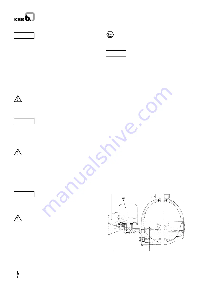
If a constant-level oiler is provided, screw same into the tapping
hole provided in the bearing bracket prior to adding the oil (see
6.1.1).
On cooled bearing brackets, fitting the constant-level oiler is
difficult due to the position of the cooling line. The connection
elbow of the constant-level oiler must be screwed in separately,
after having removed the protective cage and oil reservoir.
Afterwards, screw the oil reservoir back on and cover with the
protective cage.
The connection between bearing bracket and constant-level
oiler shall be sealed with PTFE tape, if necessary.
The operating data, the oil level, if applicable (6.1.1), and the
direction of rotation (6.1.4) must have been checked. The pump
must have been primed (6.1.3).
Also verify the following:
-
Make sure that the unit has been properly connected to the
electric power supply and is equipped with all protection
devices.
-
Make sure that all auxiliary lines (5.4.1) are connected and
functioning.
-
If the pump has been out of service for a longer period of
time, proceed in accordance with section 6.4.
On pumps delivered without a baseplate, the leakage line (part
No. 710.22) must be added as well.
6.1.1
Lubricants
Oil lubricated bearings
The bearing bracket has to be filled with lubricating oil. The oil
quality required is outlined in section 7.2.2.3 and the quantity in
section 7.2.2.4.
Oil level in reservoir
during filling procedure
Vent / Filler
plug
Oil level
sight glass
Position of reservoir for topping
up oil
Oil level in bearing bracket
and connection elbow
Fig. 9
Oil fill
Procedure:
Remove the protective cage of the constant-level oiler.
Unscrew vent plug. Pour in the oil through the vent plug tapping
hole after having hinged down the reservoir of the
constant-level oiler until oil appears in the vertical portion of the
connection elbow (Fig. 9).


