RPH
7
The casing cover is designed for holding the discharge-side
casing wear ring, if this is required for balancing the axial thrust.
The casing cover includes the heating or cooling chamber for
the shaft seal, if required.
For handling combustible fluids, the pump casing must
be made of ductile material with a maximum magnesium
content of 7.5 % (see EN 13463-1). This is a standard feature
in all KSB supplies.
4.3.1.1 Position of pump feet
Generally centreline pump feet.
Centreline pump feet are generally specified by API 610,
10th edition.
Fig. 3
Casing with centreline pump feet
4.3.1.2 Nozzle positions
Axial inlet nozzle, radial discharge nozzle pointing vertically
upwards on pumps from DN 250 or with a nominal impeller
diameter from 500 and on pump size 200-401. All other pumps
with tangential discharge nozzle pointing vertically upwards.
4.3.2
Impeller
Closed radial impeller. Impellers are supplied with wear rings
both on the suction and the discharge side or only on the suction
side.
Wear rings are locked with grub screws.
(can also be locked with three weld spots).
Balancing:
Axial thrust is balanced by means of sealing gap and balancing
holes. The size of the balancing holes depends on the inlet
pressure.
For high inlet pressures and thus impellers without balancing of
axial thrust, the discharge-side casing and impeller wear rings
are not fitted.
4.3.3
Shaft seal - Mechanical seal
Mechanical seal designs and types other than specified
herein shall only be used in exceptional cases and only
after prior consultation with the KSB factory.
The relevant seal version is shown in the mechanical seal
drawing.
4.3.4
Bearings
4.3.4.1 Design specifications
The shaft is supported by oil lubricated rolling element bearings.
The motor end bearing is a fixed bearing whose axial bearing
clearance limits the axial movement of the rotor. The standard
motor end bearing is a paired angular contact ball bearing. For
high inlet pressures, a triple bearing assembly is used (see
section 9, design variants).
The bearing brackets are provided with oil bath lubrication. Both
oil ring lubrication and oil mist lubrication are available as
special pump designs.
On the standard pump design, the bearing bracket is uncooled.
A cooled bearing bracket is available as special pump design.
During pump standstill the oil level can be checked against the
mark next to the oil level sight glass.
4.3.4.2 Bearing bracket designation
B 03
Size code (based on dimensions of seal chamber,
shaft end and bearings)
Back pull-out bearing bracket
For the applicable bearing bracket version please refer to the
data sheet.
4.3.4.3 Bearings used and bearing design
KSB designation
FAG designation
SKF designation
B.MUA
B. MP. UA
BECBM
Standard bearing assembly
Bearing
b
k t
Rolling element bearing
bracket
Pump end
Motor end
B 02
B 03
B 05
B 06
NU 211 C3
NU 213 C3
NU 316 C3
NU 324 C3
2 x 7309 B-MUA
2 x 7311 B-MUA
2 x 7315 B-MUA
2 x 7224 B-MUA
Reinforced bearing assembly (triple bearing assembly)
Bearing
b
k t
Rolling element bearing
bracket
Pump end
Motor end
B 02
B 03
B 05
B 06
NU 211 C3
NU 213 C3
NU 316 C3
NU 324 C3
3 x 7309 B-MUA
3 x 7311 B-MUA
3 x 7315 B-MUA
3 x 7224 B-MUA
4.3.5
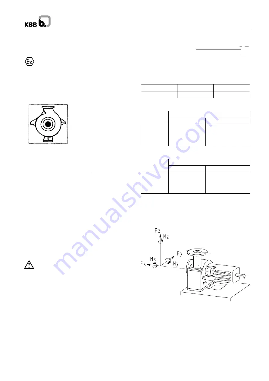
Permissible forces and moments at the pump
nozzles
RPH pumps are designed to withstand higher piping forces and
moments than required by API 610, tables 2-1A and 2-1B.
Forces and moments of RPH
D01046
Discharge nozzle
Suction nozzle


