LCC
13
Caution
lubricant should be used. Contact your GIW/KSB
representative for a recommendation. At higher speeds, or
in hotter ambient conditions, temperatures can rise to
210°F (100°C). Slightly higher temperatures may be seen
for a brief period during the breaking in of new bearings.
The unit should be shut down immediately if temperatures
rise to 250°F (120°C).
Bearing Assembly
Approximate Oil Capacity
liters (quarts)
35 mm
0.75 ( 0.75 )
50 mm
1.0 ( 1.0 )
70 mm
1.75 ( 2.0 )
100 mm
3.0 ( 3.25 )
125 mm
6.0 ( 6.5 )
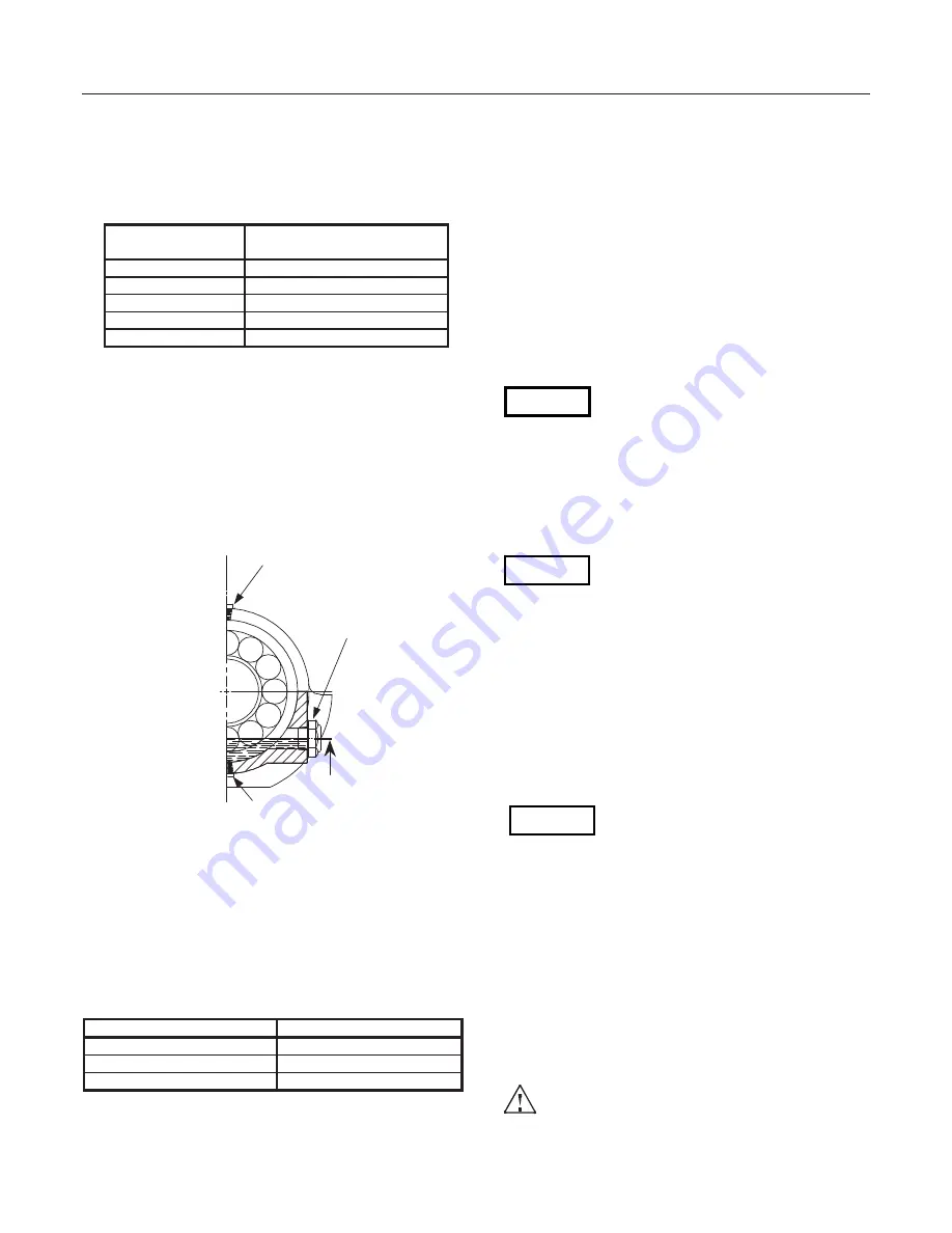
Do not overfill the bearing assembly. The capacities listed
above are approximate. When filling the bearing housing,
the oil level must be at the centerline of the oil level sight
glass when the shaft is not turning. This is the ”cold level”
and will change as the pump runs and the oil becomes
suspended in the bearings.
The constant oil leveler is no longer available. It is not
recommended for use since it can increase oil level
when the pump is running and cause leaks at bearing
seals.
Oil level with
pump stopped
Fill plug
Oil level
sight glass
Drain plug
Underwater Operation
Bearing assemblies for use underwater should be
completely filled with oil and slightly pressurized by an oil
recirculation and filtering system. As a result, their
capacities will be several times greater than shown above
and a thinner oil will be required. Depending upon the
water temperature at the location at which the pumps are
operating, the ISO viscosity grade should be altered as
follows for mineral oil-based lubricants:
Water Temperature
ISO Viscosity Grade
0 to 20
o
C (32 to 70
o
F) 100
20 to 30
o
C (70 to 85
o
F) 150
over 30
o
C ( over 85
o
F) 200
GIW Blue oil may be used for all the above temperatures
For more information on Underwater Bearing Assemblies
see section 11.2 and 11.3
6.1.2
Shaft Seal Packing
Prior to commissioning, the gland packing supplied with
the pump must be adjusted as described in Section
7.5.16. Preformed packing rings sets from GIW / KSB are
recommend. For alternate brands, refer to packing
manufacturer’s instructions regarding installation and use
(see Section 2.7).
For gland flush supply, use suitable non-aggressive clean
water not liable to form deposits and not containing
suspended solids. Hardness should average 5 with a
ph>8. It should be conditioned and neutral with regard to
mechanical corrosion.
An Inlet Temperature of 10 to 30
o
C (50 to 85
o
F) should
produce a maximum Outlet Temperature 45
o
C (115
o
F)
when the gland is properly adjusted.
Running the pump dry will result in
increased wear on the gland packing and
shaft protecting sleeve or failure of the mechanical seal.
Mechanical Seals
Mechanical seals are precision devices, which require
special care for their proper operation. If pump is equipped
with a mechanical seal, the instruction manual for the seal
should be consulted for special storage, startup and
maintenance requirements.
Mechanical seals require safety checks
prior to start-up such as removing seal
assembly fixtures, checking axial alignment, etc. Refer to
the mechanical seal operating manual for all required
safety checks.
6.1.3
Priming the Pump and Other Checks
Before start-up, the pump, suction line and (if applicable)
the tank must be vented and primed with the liquid to be
pumped. Any valve in the suction line must be fully open.
Open all auxiliary connections (flushing, sealing, cooling
liquid, etc.) and check the through flow.
6.1.4
Checking the Direction of Rotation
The impeller must rotate in the direction
indicated by the arrow on the pump
casing. This must be verified by briefly
running the motor with the coupling or belt drive
disconnected. If the motor runs in the wrong direction of
rotation, have it corrected and verify direction of rotation
before reconnecting coupling or belts. If a Variable
Frequency Drive (VFD) or other controller is used, it is
recommended to permanently disable REVERSE and
BRAKE function during controller set up.
If motive power is applied to the pump, and it is run in the
wrong direction of rotation, even momentarily, the impeller
may unscrew causing extensive damage to the entire unit.
This is especially important during initial start up as the
impeller may not be fully torqued onto the pump shaft.
6.1.5
Cleaning the Plant Piping
The cleaning operation mode and duration for
flushing and pickling service must be matched to
the casing and seal materials used.
Fig. 6.1.1: Oil fill, drain and level
Caution
Caution
Содержание GIW LCC 100-400
Страница 27: ...LCC 27 NOTES ...
Страница 34: ......


