5 Installation at Site
22 of 62
Etanorm V
1228.87/01-EN
Mounting the motor
801
515
914.24
341
901.57
920.75
732
210
712
902.11
920.11
68-3.02
920.14
920.06
550.46
905
901.11
400.06
68-3.01
920.34
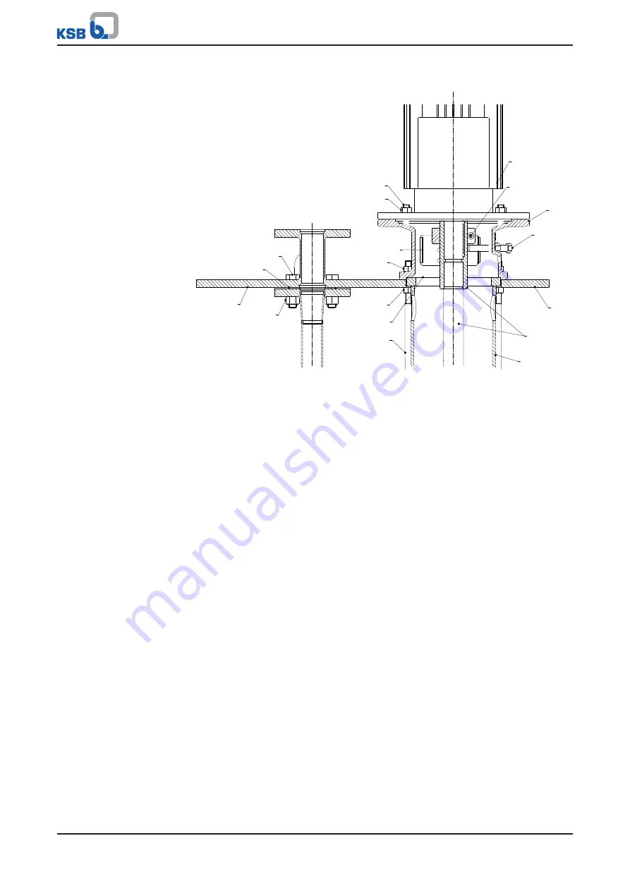
Fig. 8:
Fastening the pump with motor
ü
Shaft 210 is locked in drive lantern 341 with two bolts 901.57.
ü
Locking ring 515 has been loosened and can easily be moved on the coupling
shaft.
ü
Screw 914.24 has been loosened if necessary.
ü
The shaft of electric motor 801 and the coupling bore of shaft 210 have been
checked for rust and deposits or deformations caused during transport; remedial
action has been taken as required.
1. Insert the motor shaft into the coupling bore of shaft 210.
2. Fit the motor flange in drive lantern 341 and fasten it with studs 902.11 and
hexagon nuts 920.11.
The axial position is correct when shaft 210 and the motor shaft have been
assembled in the position they are closest to each other. This is the case when
the motor shaft end abuts the coupling inside the coupling sleeve.
Содержание Etanorm V
Страница 1: ...Vertical Low pressure Pump Etanorm V Design W Operating Manual ...
Страница 60: ......
Страница 61: ......


