4 Description
19 of 76
EtaLine Pro
1168.87/01-EN
4.6 Configuration and function
1
2
3
4
5
6
7
8
9
10
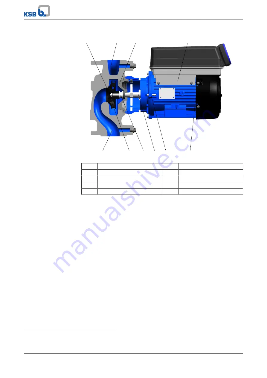
Fig. 4:
Sectional drawing
1
Clearance gap
2
Discharge nozzle
3
Casing cover
4
Drive unit
5
Suction nozzle
6
Impeller
7
Shaft seal
8
Shaft
9
Rolling element bearing
10
Rolling element bearing
Design
The pump is designed with a radial fluid inlet (suction nozzle) and a radial fluid
outlet (discharge nozzle) arranged on the same axis. The hydraulic system is rigidly
connected to the motor of the drive unit via a shaft. The shaft is dynamically
balanced.
Function
The fluid enters the pump via the suction nozzle (5) and is accelerated outward by
the rotating impeller (6). In the flow passage of the pump casing the kinetic energy
of the fluid is converted into pressure energy. The fluid is pumped to the discharge
nozzle (2), where it leaves the pump. The clearance gap (1) prevents any fluid from
flowing back from the casing into the suction nozzle. At the rear side of the impeller,
the shaft (8) enters the hydraulic system through the casing cover (3). The shaft
passage through the casing cover is sealed towards the atmosphere with a shaft seal
(7). The shaft runs in rolling element bearings (9 and 10), which are supported by the
drive unit (4). The drive unit (4) is connected to the pump casing and clamps the
casing cover (3).
Sealing
The pump is sealed by a standardised mechanical seal.
4.7 Noise characteristics
The surface sound pressure level LpA for all sizes of the pump set is ≤ 69 dBA.
2)
2
Surface sound pressure level as per ISO 3744 and DIN EN ISO 20361 ; valid for a pump operating range of Q/
QBEP = 0.8 - 1.1 and non-cavitating operation. If noise levels are to be guaranteed: Add +3 dB for measuring
and constructional tolerance.


