✓
The pump's installation position has been checked.
The plate can be seen from above.
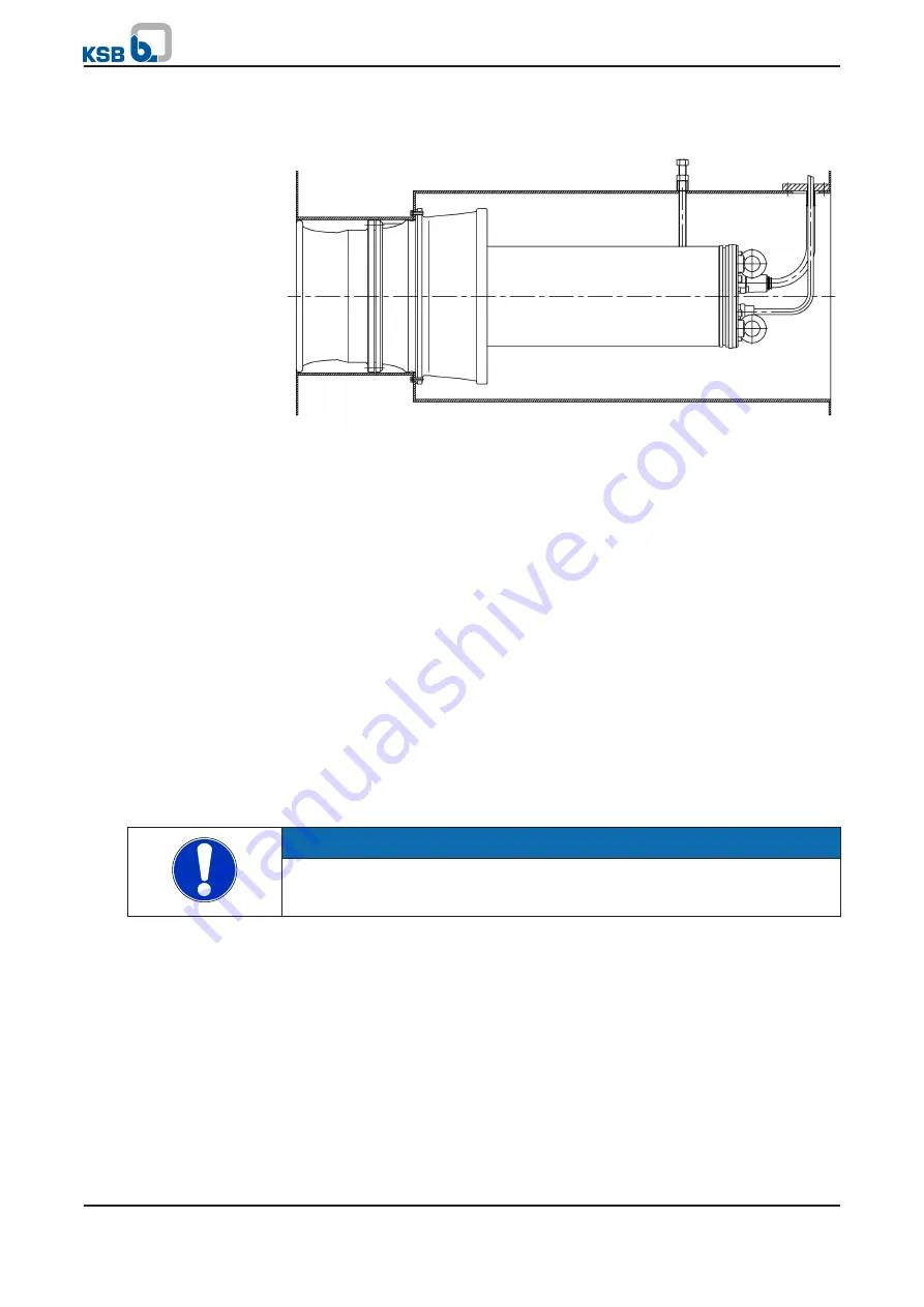
Fig. 9: Installing the pump set in the discharge tube
1.
Fasten the diffuser casing to the discharge tube with screws.
The number and size of the screws required depends on the pump size.
2.
Centralize the motor with 3 adjusting screws offset from each other by 120°.
3.
Sealing off the cable entry into the discharge tube
After the pump has been installed in the discharge tube, run the cables through
the opening provided in the side of the discharge tube.
Do not pull the cables too tight to prevent kinking.
⇨
Observe the bending radius of the cables.
4.
Integrate the discharge tube section in the pipeline.
5.4 Electrical system
5.4.1
Information for planning the control system
For the electrical connection of the pump set observe the wiring diagrams contained
in the Annex.
The pump set is supplied with power cables; it is wired for DOL starting. Star-delta
starting is also possible.
NOTE
When laying a cable between the control system and the pump set's connection
point, make sure the number of cores for the sensors is sufficient. A minimum cross-
section of 1.5 mm
²
(AWG 15) is required.
5.4.1.1
Overload protection
1.
Protect the pump set against overloading by a thermal time-lag overload
protection device in accordance with IEC 947 and local regulations.
2.
Set the overload protection device to the rated current specified on the name
plate.
5.4.1.2
Frequency inverter operation
The pump set is suitable for frequency inverter operation as per IEC 60034-17.
When selecting a frequency inverter, check the following details:
▪
Data provided by the manufacturer
Selection
5 Installation at Site
22 of 68
Amacan P


