


TC · Edition 07.14
13
บริษัท เอดีดี เฟอร์เนส จ ำกัด
ADD FURNACE CO.,LTD.
44 ซอยบรมราชชนนี
70 ถนนบรมรำชชนนี แขวงศำลำธรรมสพน์ เขตทวีวัฒนำ กรุงเทพฯ 10170
โทร
: 02-888-3472
โทร
:
ออกแบ
บ
:
08-08-170-170
แฟกซ์
: 02-888-3258
https://www.add-furnace.com E-mail:
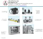
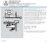
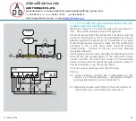
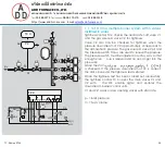
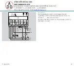
1 .1 .7 TC 2 in a multiple burner system with 3 valves
installed in series
When using slow opening main valves (V1 and V2), auxiliary
valves (V3 and V4) must be used for the supply and discharge of
the test volume V
P
.
Tightness control TC 2 checks the central shut-off valve V1, the
gas solenoid valve V2 and the auxiliary valves V3 and V4 for
tightness.
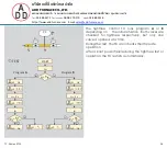
Valve V2 can only be checked for tightness when the pressure
downstream of V2 approximately corresponds to the atmos-
pheric pressure and the volume downstream of valve V2 is 5 x
V
P
. The gas solenoid valve VAS and the pressure switch DG
VAS
are used to relieve the pressure. The pressure switch must be
adjusted in such a way so that enough pressure is relieved and
no air can get into the pipework.
Once the tightness test has been carried out successfully, the
tightness control TC 2 opens the main valves V1 and V2 with the
OK enable signal and enables the downstream burner control
units.
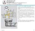
V3 and V4: quick opening, nominal size is dependent on test
volume V
P
and inlet pressure p
u
, see page 34 (Project plan-
ning information), but is at least DN 15.
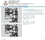
A
= Supply and signal forwarding
B
= Automatic burner control unit
C
=
Gas solenoid valves
PZ = Internal pressure sensor of the TC for the comparison
of inlet pressure p
u
and interspace pressure p
z
PZ = Pressure switch DG
VAS
for monitoring the pressure
down- stream of V2
TC 2
TC 2
PZ
p
u
2
V1
V2
p
u
p
Z
V
P
V3
L1(+)
N(-)
PE
OK
1 3 5 6
A
TC 2
1 2 3
B
V2
K1
DG
VAS
1 2 3
C
V1
K1
VAS
V3
V4
V4
V
A
S
PZ
D
G
V
A
S


