


TC · Edition 07.14
11
บริษัท เอดีดี เฟอร์เนส จ ำกัด
ADD FURNACE CO.,LTD.
44 ซอยบรมราชชนนี
70 ถนนบรมรำชชนนี แขวงศำลำธรรมสพน์ เขตทวีวัฒนำ กรุงเทพฯ 10170
โทร
: 02-888-3472
โทร
:
ออกแบ
บ
:
08-08-170-170
แฟกซ์
: 02-888-3258
https://www.add-furnace.com E-mail:
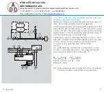
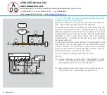
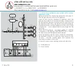
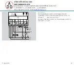
1 .1 .5 TC 2 with two gas solenoid valves and one
auxiliary valve for discharge
Tightness control TC 2 checks the gas solenoid valves V1
and V2 and the auxiliary valve V3 for tightness.
It must be ensured that the interspace is vented during the
2-second opening time. This is not guaranteed by the gas
pressure regulator downstream of V2. The test volume V
P
is
thus discharged into the combustion chamber or into a
safe area. Auxiliary valve V3 can also be used as a pilot
gas valve. Since valve V2 remains closed during the test, it
can also be a slow opening motorized valve VK.
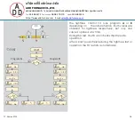
Once the tightness test has been carried out successfully,
the tightness control forwards the OK enable signal to the
automatic burner control unit GFA. The pilot valve output
of the automatic burner control unit GFA opens the gas
solenoid valves V1 and V3 simultaneously. The main valve
output opens gas solenoid valve V2. The burner starts.
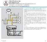
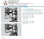
V1 and V2: quick or slow opening valves with start rate.
V3: quick or slow opening valve with start rate, nominal
size is dependent on test volume V
P
and inlet pressure
p
u
, see page 34 (Project planning information), but is at
least DN 15.
A
=
Supply
and
signal
forwarding
B
= Automatic
burner control unit
C
= Gas
solenoid valves
PZ = Internal pressure sensor of the TC for the comparison
of inlet pressure p
u
and interspace pressure p
z
TC 2
TC 2
V3
PZ
p
u
2
V1
V2
p
u
p
Z
V
P
L1(+)
N(-)
PE
OK
GFA
1 2 3
B
1 3 5 6
A
TC 2
1 2 3
C
V1 V3
V2


