background image

BIO · Edition 09.22

EN-13


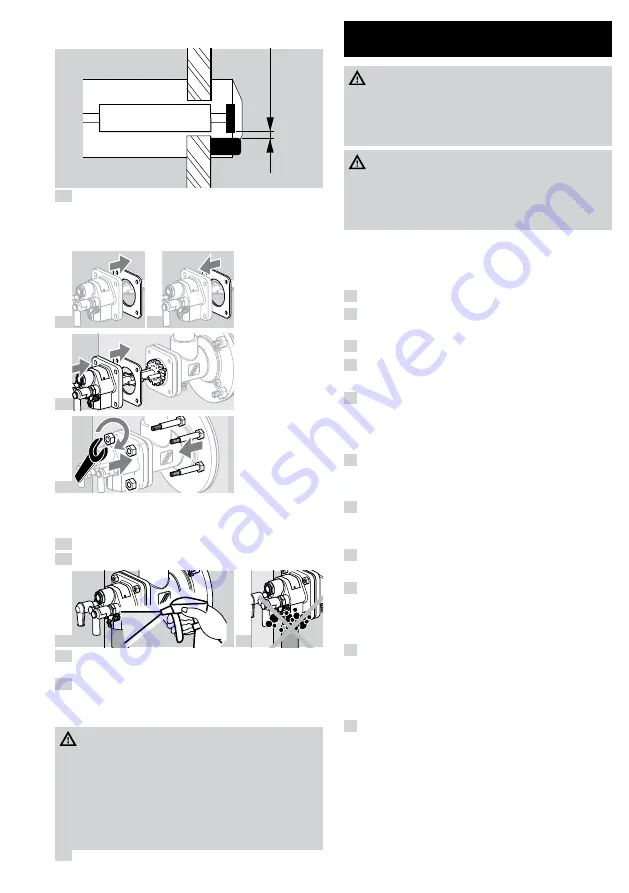
Distance of spark electrode from ground pin or gas 
nozzle: 2 ± 0.5 mm (0.08 ± 0.02").

± 

0,5

 mm

(0.08 

± 

0.02 

inch)

 6 

When the furnace chamber has cooled down, 

check the burner tube and burner block through 
the furnace flange.


Replace the gas housing gasket.

 7 


 8 


 9 


 10 


Tighten burner insert in a crosswise fashion: BIO(A) 

50 to 100 with max. 15 Nm (11 lb ft), BIO 125 to 

140 with max. 30 Nm (22 lb ft).

 11 

Connect the system to the electrical power supply.

 12 

Open the gas and air supply.

 13 


 14 

 15 

Set the burner to low fire and compare the pressure 

settings to those stated in the acceptance report.

 16 

Set the burner to low and high fire several times 

while monitoring the pressure settings, flue gas 
values and flame patterns.

 DAnGeR

Risk of explosion and poisoning in case of burner 
adjustment with insufficient air!


– Adjust the gas and air supply so that the burner 

is always operated with excess air – otherwise 
CO will form in the furnace chamber. CO is 
odourless and poisonous! Conduct a flue gas 
analysis.

 17 

Produce a maintenance report.

8 AssIstAnCe In tHe eVent oF 
MALFUnCtIon

 DAnGeR

Electric shocks can be fatal!


– Before working on possible live components, 

ensure the unit is disconnected from the power 
supply.

 DAnGeR

Risk of injury!
Burner heads have sharp edges.


– Burner inspection must only be performed by 

authorized trained personnel.


If no issues are found when checking the burner, 
proceed to the automatic burner control unit and 
check for faults in accordance with the relevant 
operating instructions.

 ?  Fault
 ! 

 Cause
  •   Remedy

 ?  Burner does not function.
 ! 

 Valves do not open.
  •  Check the voltage supply and wiring.

 ! 

 Tightness control signals a fault.
  •  Check the valves for tightness.
  •  Note the tightness control operating instruc-

tions.

 ! 

 Control valves do not move to low-fire rate posi-

tion.

  •  Check the impulse lines.

 ! 

 Gas inlet pressure is too low.
  •  Check the filter for dirt.
  •  Check the gas supply.

 ! 

 Air inlet pressure is too low.
  •  Check the fan and air supply.

 ! 

 Gas and air pressures on the burner are too low.
  •  Check the restrictors.
  •  Check/adjust the start rate setting, see operat-

ing instructions for solenoid valve.

 ! 

 Automatic burner control unit does not function 

correctly.

  •  Check the device fuse.
  •  Note the automatic burner control unit operat-

ing instructions.

 ! 

 Automatic burner control unit signals a fault.
  •  Check the ionization cable.
  •  Check the ionization current. The ionization 

current must be at least 5 μA – stable signal.

  •  Check whether the burner is adequately 

grounded.

  •  Note the automatic burner control unit operat-

ing instructions.

Содержание BIO 100

Страница 1: ...st be installed and commissioned in accordance with the regulations and standards in force These instructions can also be found at www docuthek com 1 2 Explanation of symbols 1 2 3 a b c Action Instruction 1 3 Liability We will not be held liable for damage resulting from non observance of the instructions and non com pliant use 1 4 Safety instructions Information that is relevant for safety is in...

Страница 2: ...s D Coke oven gas town gas G Propane propane butane butane M Propane propane butane butane with mixer L Low calorific value gas F biogas L Torch R Reduced capacity X X mm length of steel tube as of furnace flange L1 X X mm distance from furnace flange to front edge of burner head L2 X Burner head identifier A Z Construction stage B With purge air bore holes H High temperature version Z Special ver...

Страница 3: ...3 4 Flat flame burner block For industrial furnaces and kilns and for burning in an open combustion chamber Control High Low High Low Off continuous lim ited turndown Type of burner head K Capacity range 40 100 3 5 Burners with attachment tube Position of the burner head near the interior furnace wall L2 LO 50 mm L2 LO 50 mm LO 1 Do not fit the attachment tube 1 directly in the furnace wall Furnac...

Страница 4: ... units to prevent mechanical stress or transmission of vibration Ensure that the gaskets are undamaged DANGER Risk of explosion Ensure the connection is air tight On delivery the threaded gas connection is situated opposite the air connection it can be rotated in increments of 90 3 10 Connection to ANSI NPT An adapter set is required for connection to ANSI NPT see page 14 9 Accessories Type Gas co...

Страница 5: ...GER Electric shocks can be fatal Before working on possible live components ensure the unit is disconnected from the power supply For the ignition and ionization cables use un screened high voltage cable FZLSi 1 6 up to 180 C 356 F Order No 04250410 or FZLK 1 7 up to 80 C 176 F Order No 04250409 Z I Flame rod I Install the ionization cable well away from mains cables and interference from electrom...

Страница 6: ...ischarge the test volume into the furnace chamber DANGER Risk of poisoning Open the gas and air supply so that the burner is always operated with excess air otherwise CO will form in the furnace chamber CO is odourless and poisonous Conduct a flue gas analysis The burner must only be commissioned by authorized trained personnel If the burner does not ignite even though the auto matic burner contro...

Страница 7: ... pres sure loss in the furnace combustion chamber Add positive pressures or subtract negative pressures The differential gas pressure Δpgas measured on the integrated gas measuring orifice is independent of the furnace chamber pressure WARNING If reducing fittings or manual valves with internal thread are installed Δpgas on the integrated gas measuring orifice is reduced Reducing fitting with inte...

Страница 8: ...The burner must only be ignited at low fire rate between 10 and 40 of the rated capacity Qmax see page 2 2 1 Type label 5 Reduce the air supply on the air control valve and set the desired low fire rate e g using a limit switch or mechanical stop On air control valves with bypass the bypass orifice should be determined on the basis of the required flow rate and the existing supply pressure if requ...

Страница 9: ...0 50 mbar Check flame stability and ionization current The gas and air pressure of the integrated pilot must be higher than the gas and air pressure of the main burner 6 COMMISSIONING 6 1 Igniting and adjusting the burner WARNING Ensure adequate ventilation of the furnace chamber before each burner start The burner body will become hot during operation with preheated combustion air Provide protect...

Страница 10: ... μA Z I 18 Monitor flame formation 19 Adjust the low fire rate settings if required 20If no flame is detected see page 13 8 Assis tance in the event of malfunction 6 3 Setting the high fire rate 1 Set the air and gas circuit of the burner to high fire while continuously monitoring the flame Avoid CO formation always operate the burner with excess air when starting up Burners without gas measuring ...

Страница 11: ...igh fire several times while monitoring the pressure settings flue gas values and flame patterns 4 Remove the measuring devices and close off the test nipples tighten the grub screws 5 Block and seal the adjusting elements 6 Induce a flame failure e g by pulling the terminal boot off the flame rod The flame detector must close the gas safety valve and signal a fault 7 Switch the system on and off ...

Страница 12: ...age the surface of the insulation Avoid the formation of dust 1 2 3 If the burner insert is dismantled the gas housing gasket will have to be renewed 4 Place the burner insert in a safe place Depending on the amount of dirt or wear replace the spark electrode flame rod and dowel pin during servicing see page 12 7 1 Checking the spark electrode and flame rod Check burner head for dirt and thermal c...

Страница 13: ...nts ensure the unit is disconnected from the power supply DANGER Risk of injury Burner heads have sharp edges Burner inspection must only be performed by authorized trained personnel If no issues are found when checking the burner proceed to the automatic burner control unit and check for faults in accordance with the relevant operating instructions Fault Cause Remedy Burner does not function Valv...

Страница 14: ...50120009 9 2 Adapter set 8 8 BIO 125 140 BIO 50 100 BIOA 65 For connecting burners BIO BIOA to NPT ANSI connections Burner Adapt er set Gas con nection Air con nection Order No BIO 50 BR 50 NPT 14 NPT 1 11 5 NPT 74922630 BIO 65 BR 65 NPT 14 NPT 1 11 5 NPT 74922631 BIOA 65 14 NPT Ø 1 89 75456281 BIO 80 BR 80 NPT 14 NPT 2 11 5 NPT 74922632 BIO 100 BR 100 NPT 1 11 5 NPT 2 11 5 NPT 74922633 BIO 125 BR...

Страница 15: ...2 F BIOA up to 200 C 392 F BIOW up to 600 C 1112 F REACH Regulation applies to BIOW only Information pursuant to REACH Regulation No 1907 2006 Article 33 Insulation contains refractory ceramic fibres RCF aluminium silicate wool ASW RCF ASW are listed in the Candidate List of the European REACH Regulation No 1907 2006 10 1 REACH Regulation applies to BIOW only Information pursuant to REACH Regulati...

Страница 16: ...lfilled RoHS II 2011 65 EU The partly completed machine may only be com missioned once it has been established that the machine into which the product mentioned above is to be incorporated complies with the provisions of the Machinery Directive 2006 42 EC Elster GmbH 14 CERTIFICATION 14 1 Eurasian Customs Union The products BIO meet the technical specifications of the Eurasian Customs Union 14 2 C...

Отзывы: