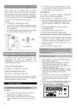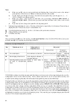
5.2 Operating elements
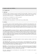
CAUTION
To avoid damage to electronics, be
certain that the area around the meter is dry before
removing the electronics compartment cover.
The operating elements are accessible after
removing the cover of the electronics section using
the special wrench.
CAUTION
Do not damage screw thread, never
allow dirt to accumulate, and make sure it is well
greased at all times.
Display, 1
st
line
Display, 2
nd
line
Display, 3
rd
line
Cursor symbols described below
q
v
q
m
S
T
P
u
Volumetric flow rate
Mass flow rate
Totalizer value
Measured / Set temperature value
Measured / Set pressure value
Velocity of medium
Keys for programming the Signal Converter, refer
to Sect. 5.4 for the functions of keys.
6
o
Magnetic Sensors to program the converter by
means of a hand-held bar magnet without having
to open the housing, refer to Sect. 6.3. Function
of sensors is same as keys
. Hold the bar
magnet by the cap. Apply other end of the magnet
(north pole) to the glass pane above the magnetic
sensors. Sensor or key response is acknowledged
by symbols appearing in 1
st
line of display.
xxx on the display is used to describe the type of
the meter. It can be :
1. AGA - Natural Gas Meter (AGA)
2. FAD - Free Air Delivery
3. HM - Heat Meter
4. NHM - Net Heat Meter
5. STD - Standard
10
Содержание VFM 5090
Страница 1: ...4 2001 Vortex flowmeter Installation and operating Instructions VFM 5090 I ...
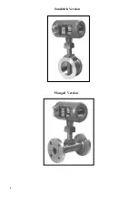
Страница 6: ...Sandwich Version Flanged Version 3 ...
Страница 55: ......
Страница 56: ...13 Nameplates of VFM 5090 I Ex 51 52 ...
Страница 66: ...DIMENSION DETAILS 62 ...


