TECHNICAL DATA
8
107
OPTISWIRL 4200
www.krohne.com
02/2022 - 4003930810 - MA OPTISWIRL4200 R10 en
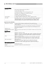
Recommended flow velocities
Liquids
3
,
4
0.3…7 m/s / 0.98…23 ft/s (optional up to 10 m/s / 32.8 ft/s taking cavitation into account)
Gases and steam
3
2.0…80 m/s / 6.6…262.5 ft/s
DN15: 3.0…45 m/s / 9.8…148 ft/s; DN25: 2.0…70 m/s / 6.6…230 ft/s
3
These values represent the absolute limits of flow velocities. For more detailed information for your specific
application refer to
Intended use on page 7.
4
v
min
= 0.7 m/s / 2.3 ft/s in SIL mode
Other conditions
Ingress protection
Compact version:
Signal converter in aluminium housing, IP66/67
Signal converter in stainless steel housing, IP66, IP68, IP69K
Remote version:
Signal converter in aluminium housing, IP66/67; flow sensor housing, IP66/67
Signal converter in stainless steel housing, IP66, IP68, IP69K;
flow sensor housing, IP66, IP68, IP69K
Installation conditions
Inlet section
15 DN without disturbing flow
20 DN after a pipe diameter reduction
20 DN after a single bend 90°
30 DN after a double bend 2 x 90°
40 DN after a double three-dimensional bend 2 x 90°
50 DN after a control valve
2 DN before a flow straightener;
8 DN after a flow straightener
Outlet section
5 x DN
Materials
Flow sensor and process
connections
Standard: 1.4404 / 316L
Option: Hastelloy
®
C-22 on request
Electronics housing
Aluminium die-cast, two-layer coating (epoxy/polyester)
Option: 1.4409 / 316L / A 351-CF3M
Option: die-cast aluminium with finish for advanced requirements
Pressure sensor gasket
Standard: FPM
Option: FFKM
Measuring tube gasket
(Pick-up)
Standard: 1.4435 / 316L
Option: Hastelloy
®
C-276
Selection depends on flow sensor material / medium.
Process connections
Flange version
DIN EN 1092-1
DN15...300, PN16...100 (higher pressures on request)
ASME B16.5
1/2...12", 150…600 lb (higher pressures on request)
JIS B2220
DN15...300, 10…20 K (higher pressures on request)
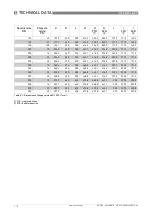
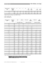
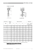
For detailed information on combination flange/pressure rating, refer to section "Dimensions and weights".


