


CONTENTS
2
www.krohne.com
10/2016 - 4005626301 - QS OPTISONIC 1400 R01 en
OPTISONIC 1400
1 Safety instructions
4
2 Installation
5
2.1 Scope of delivery............................................................................................................... 5
2.2 Device description ............................................................................................................ 6
2.2.1 Field housing........................................................................................................................... 7
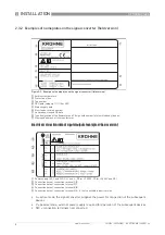
2.3 Nameplates ...................................................................................................................... 7
2.3.1 Nameplate for the measuring sensor (field version) ............................................................. 7
2.3.2 Examples of nameplates on the signal converter (field version) .......................................... 8
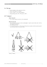
2.4 Storage ............................................................................................................................. 9
2.5 Transport .......................................................................................................................... 9
2.6 Pre-installation requirements ....................................................................................... 10
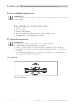
2.7 General requirements .................................................................................................... 10
2.7.1 Vibration ................................................................................................................................ 10
2.8 Installation conditions .................................................................................................... 11
2.8.1 Inlet and outlet ...................................................................................................................... 11
2.8.2 Bends in 2 or 3 dimensions................................................................................................... 11
2.9 T-section ......................................................................................................................... 12
2.10 Bends ............................................................................................................................ 12
2.11 Open feed or discharge ................................................................................................ 13
2.12 Position of pump........................................................................................................... 13
2.13 Control valve................................................................................................................. 13
2.14 Down going pipeline over 5 m /16 ft length ................................................................. 14
2.15 Mounting position ......................................................................................................... 14
2.16 Installation .................................................................................................................... 15
2.16.1 Path configurations and coding .......................................................................................... 15
2.16.2 Calculation of the transducer position ............................................................................... 16
2.16.3 Determine transducer position with a paper roll............................................................... 17
2.16.4 Marking the transducer positions on the pipe ................................................................... 18
2.16.5 Installing the Hot tap device ............................................................................................... 20
2.16.6 Installing the Cold tap device.............................................................................................. 23
2.16.7 Alignment of the transducers............................................................................................. 26
2.17 Mounting the field housing, remote version ................................................................ 27
2.17.1 Pipe mounting ..................................................................................................................... 27
2.17.2 Turning the display of the field housing version ................................................................ 28
3 Electrical connections
29
3.1 Safety instructions.......................................................................................................... 29
3.2 Signal cable (remote versions only)............................................................................... 29
3.3 Power supply .................................................................................................................. 31
3.4 Laying electrical cables correctly .................................................................................. 32
3.5 Inputs and outputs, overview ......................................................................................... 33
3.5.1 Combinations of the inputs/outputs (I/Os) ........................................................................... 33
3.5.2 Description of the CG-number.............................................................................................. 34
3.5.3 Fixed, non-alterable input/output versions.......................................................................... 35
3.5.4 Alterable input/output versions............................................................................................ 36
4 Technical data
37


