background image

22

OPTIMASS

3

PROFIBUS PA DEVICE (MBP INTERFACE & PA PROFILE 3.01

PLC

PLC

PC

PC

PROFIBUS DP (up to 12 Mbit/s)

K R O H N E

          1 


  2                 3                 4            

 5               6

K R O H N E

          1 


  2                 3                 4            

 5               6

1000

Power
Supply

900

800

700

600

500

400

300

200

kg/ h

100

RP

KR O H N E

H250

SN

 586 

677 /01-03

MC

 H250/RR/ M9/K2 /ESK- Z

C

 K2 5.2 

1.4571

F

 CIV 

25 

1.4571

MD

 1997

C2H50H

D

 0.93 

kg/l

V

 2.5 

mPa.s

T

 23.5 

C

P

 0.4 

MPa

FI A   1025

kg

0

3

6

8

7

2

Segment
coupler/link

PROFIBUS-PA

PROFIBUS-PA

Analogue I/O 

module

HART Device

4-20 mA

Control system 

(PLC) Class 1 

master

Engineering or operation 

control tool. Class 2 master

IIs

ss

su

ue

ed

d

S

Siig

gn

na

all  C

Co

on

nvve

errtte

err

A

Ap

pp

plliic

ca

attiio

on

n  P

Prro

og

grra

am

m

S

Syys

stte

em

m  IIn

ntte

eg

grra

attiio

on

n  

Month/

Year

Hardware

Firm-

ware

Hardware

Software

Driver

Version

Model Name as

used in the GSD: 

11/06

'MFC300 Signal

Converter with MBP

Interface and PA

Profile 3.01

("Profibus PA

Device")

V2.2.1/

061117

• Simatic PCS7
• Others

• HW Config
• Others

GSD

(Manufacturer specific, for

standard DP/PA segment

coupler )

KR014511.GSD

"MFC300 (MBP)
Rev. 1"

GSD

(Manufacturer specific, for

segment coupler SK2/SK3 of

P&F)

YP014511.GSD

"YP0 MFC300

(MBP) Rev.1"

GSD

(Profile specific, for standard

DP/PA segment coupler)

PA139742.GSD

"Flow,dens,temp
3AI, 1TOT (PhyL
1)"

Laptop/ PC

PDM 

A

6.0

DD

4511 0300 01

Laptop/ PC

Pactware

DTM

(generic Flow DTM)

0300_1030001_F

DT12.exe

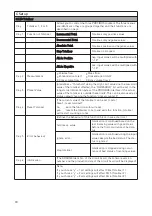
3.1 Software history

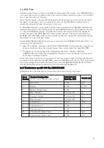
3.2 PROFIBUS PA System Architecture

The diagram above shows a typical instrumentation with PROFIBUS PA devices with MBP inter-
face in hazardous and non-hazardous locations, including connections of conventional devices
(e.g. with 4-20mA signals) ina a PROFIBUS network.

The PROFIBUS PA is normally connected to a segment coupler which, among other things,
carries out the conversion to the PROFIBUS DP.

Further information on the planning and operation of PROFIBUS PA networks can be found in
the KROHNE brochure “Fundamentals PROFIBUS” which can be downloaded from the
KROHNE homepage http://www.krohne.com or contact “KROHNE Marketing”.

Содержание OPTIMASS MFC 300

Страница 1: ...FC C 3 30 00 0 P PR RO OF FI IB BU US S D DP P R RS S4 48 85 5 d de ev vi ic ce e w wi it th h P PA A p pr ro of fi il le e M MF FC C 3 30 00 0 P PR RO OF FI IB BU US S P PA A M MB BP P d de ev vi ic...

Страница 2: ...2...

Страница 3: ...Structure of Function Block Output Values 12 2 7 Diagnosis 13 2 8 Display Parameters PROFIBUS 14 2 9 Technical Data 21 3 PROFIBUS PA DEVICE MBP INTERFACE PA PROFILE 3 01 3 1 Software History 22 3 2 PR...

Страница 4: ...ym mb bo ol ls s U Us se ed d The follwing is a guide to the meaning of the symbols used in this handbook The symbols fall into two types The rectangular symbols with blue background draws the reader...

Страница 5: ...y Responsibility for suitability and intended use of this device rests solely with the user Improper installation and operation of the device may lead to loss of warranty In addition the Terms and Con...

Страница 6: ...ait approx 10 seconds before you switch off the MFC300 after you have done both a parameter download via PROFIBUS or a manual change of a parameter value via the local display Please wait approx 15 se...

Страница 7: ...thers HW Config others GSD Manufacturer specif ic for standard DP PA segment cou pler KR014510 GSD MFC300 RS 485 Rev 1 GSD Profile specific for standard DP PA seg ment coupler PA039742 GSD Flow dens t...

Страница 8: ...B B D C D C I I I I 5V R2 R1 R1 I 110nH R1 390 R2 220 3 B B D C D C I I I I 5V R2 R1 R1 I 110nH R1 390 R2 220 2 1 External connection PROFIBUS DP device at low datarates connected with spur Spurs are...

Страница 9: ...data exchange of the coriolis mass flow meter MFC300 The application of the manufacturer independent Ident No 9742hex GSD file PA039742 GSD provides interchangeability of devices i e an exchange of co...

Страница 10: ...ings to select the units for local display and PROFIBUS Modifications of the units of the display will have no effect on the data transferred via PROFIBUS A master class 2 tool is required to modify t...

Страница 11: ...6 Slot 6 Index 32 If the value of SetTot changes from 2 to 0 the totaliser starts counting from the current value defined by PresetTot SetTot 2 not allowed Value is ignored totaliser remains in its la...

Страница 12: ...ven in the following tables 2 5 Profiles The MFC300 PROFIBUS RS 485 Interface supports the PROFIBUS PA Profile Version 3 01 The MFC300 PROFIBUS RS 485 Interface with PA Profile 3 01 supports the follo...

Страница 13: ...to get the quality information of the measurement value G Go oo od d n no on n C Ca as sc ca ad de e function block output value is ok and can be used without restrictions G Go oo od d C Ca as sc ca a...

Страница 14: ...ser 3 where fitted for PROFIBUS Devices the counter can be reset to zero in this menu step 1 reset counter N No o exits the function without reset Y Ye es s resets the counter and exits the func tion...

Страница 15: ...l be set in the long status information bytes of the PROFIBUS interface if the actual value of the totaliser is outside these limits This can be also used as a status output choosing the function pres...

Страница 16: ...y voltage for the PROFIBUS C5 y 2 Time Constant Time constant for this function block C5 y 3 Error Behaviour Defines the behaviour of this function block in case of errors Hold Value last valid OUT va...

Страница 17: ...blocks Only PROFIBUS values can be selected here The analogue inputs are shown with exactly the value as seen on the PROFIBUS C6 4 1 Measurement 1 line FB1 Analog inp 1 FB2 Analog inp 2 FB3 Analog inp...

Страница 18: ...6 3 Load Settings in this menu all settings can be loaded from different storage places where settings have been saved before step 1 Load Settings break Exits the menu without loading factory setting...

Страница 19: ...tion Y Ye es s quick access activated N No o quick access not activated C6 9 3 reset totaliser 3 The reset can be activated in the Quick Setup to get a quick access of the function Y Ye es s quick acc...

Страница 20: ...orted no extras D2 2 5 PB Cold Start Reset N No o terminates the function Y Ye es s PROFIBUS cold start will be carried out at once The programming mode is terminat ed N No ot te e During a PROFIBUS c...

Страница 21: ...profile PA Profile compact class B V3 01 Address range 0 126 default 126 0 to 125 via set_slave_add 0 to 126 via Local Display 126 via FACTORY_RESET 2712 Local control local display and operator inter...

Страница 22: ...ibus PA Device V2 2 1 061117 Simatic PCS7 Others HW Config Others GSD Manufacturer specific for standard DP PA segment coupler KR014511 GSD MFC300 MBP Rev 1 GSD Manufacturer specific for segment coupl...

Страница 23: ...In Out 3 Alternative wiring because the current linkage between the device and the PROFIBUS PA cable is not polarised N No ot te e Although the PROFIBUS MBP technology supports power supply via the P...

Страница 24: ...elongs to the KR014511 GSD YP014511 GSD and includes the com plete functionality concerning the cyclic data exchange of the coriolis mass flow meter MFC300 The application of the manufacturer independ...

Страница 25: ...the units for local display and PROFIBUS Modifications of the units of the display will have no effect on the data transferred via PROFIBUS A master class 2 tool is required to modify the units for PR...

Страница 26: ...rer Specific full functionality to Profile Specific interchangeable basic configuration by using a master class 2 tool IDENT_NUM BER_SELECTOR Slot 0 Index 40 change byte value to 0 After this the devi...

Страница 27: ...r coriolis mass flow devices This block provides the parameters and functions defined in PA Profile 3 01 Eight Analog Input AI function blocks as default Mass Flow Density Medium Temperature Volume Fl...

Страница 28: ...to get the quality information of the measurement value G Go oo od d n no on n C Ca as sc ca ad de e function block output value is ok and can be used without restrictions G Go oo od d C Ca as sc ca a...

Страница 29: ...B6 Totaliser 3 for PROFIBUS Devices the counter can be reset to zero in this menu step 1 reset counter N No o exits the function without reset Y Ye es s resets the counter and exits the func tion A4 S...

Страница 30: ...l be set in the long status information bytes of the PROFIBUS interface if the actual value of the totaliser is outside these limits This can be also used as a status output choosing the function pres...

Страница 31: ...y voltage for the PROFIBUS C5 y 2 Time Constant Time constant for this function block C5 y 3 Error Behaviour Defines the behaviour of this function block in case of errors Hold Value last valid OUT va...

Страница 32: ...blocks Only PROFIBUS values can be selected here The analogue inputs are shown with exactly the value as seen on the PROFIBUS C6 4 1 Measurement 1 line FB1 Analog inp 1 FB2 Analog inp 2 FB3 Analog inp...

Страница 33: ...6 3 Load Settings in this menu all settings can be loaded from different storage places where settings have been saved before step 1 Load Settings break Exits the menu without loading factory setting...

Страница 34: ...tion Y Ye es s quick access activated N No o quick access not activated C6 9 3 reset totaliser 3 The reset can be activated in the Quick Setup to get a quick access of the function Y Ye es s quick acc...

Страница 35: ...pported no extras D2 2 5 PB Cold Start Reset N No o terminates the function Y Ye es s PROFIBUS cold start will be carried out at once The programming mode is terminat ed N No ot te e During a PROFIBUS...

Страница 36: ...e_add 0 to 126 via Local Display 126 via FACTORY_RESET 2712 FDE yes separate fault discon nection electronics provided Local control local display and operator interface at device Fault current 6 mA f...

Страница 37: ...37...

Страница 38: ...38...

Страница 39: ...39...

Страница 40: ...snl net Iran KROHNE Liaison Office North Sohrevardi Ave 26 Sarmad St Apt 9 Tehran 15539 TEL 98 21 874 5973 FAX 98 21 850 1268 e mail krohne krohneiran com Italy KROHNE Italia Srl Via V Monti 75 I 2014...

Отзывы: