©
KRAMER ELECTRONICS LTD.
Issue 1-16 May 30, 2017
43
6.3.1
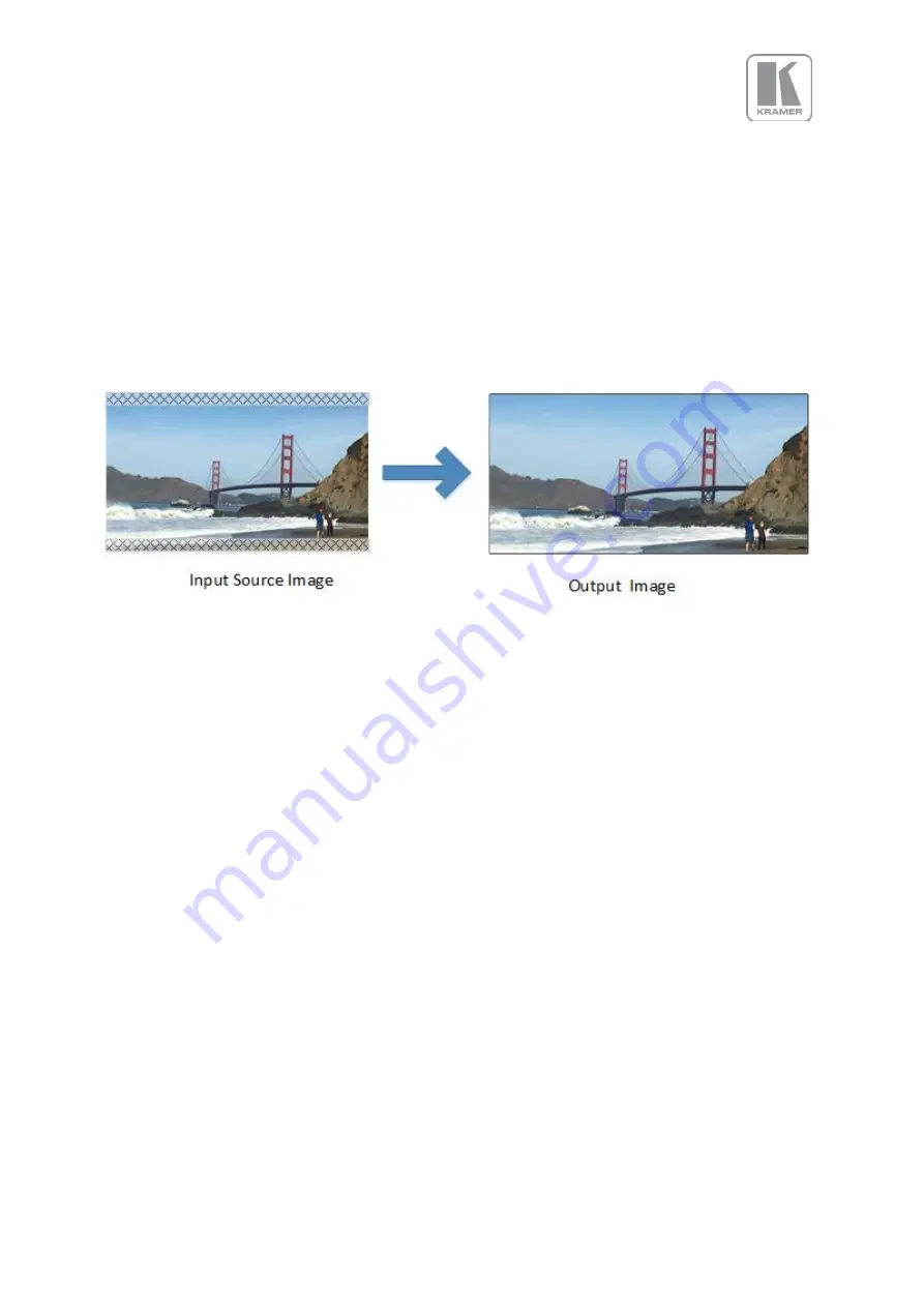
Few words about Aspect Ratio
In the example above, the aspect ratio of the input source is 1.66, but the LED wall aspect ratio is 2.
When the source and the output aspect ratios do not much, the user has three options. These options
are explained in the Picture Format section that is found under the Input/Geometry chapter of this
document.
In the example, the “Original” option was chosen maintaining the source aspect ratio. With this
option, all objects appear proportional and normal in the output image, but a portion of the source
content was disregarded. As it can be seen in the picture, a small slice of the top and the bottom of
the image has been disregarded.
Figure 4: Maintaining the Aspect Ratio Example
6.3.2
Splicing Zoom
In configurations where multiple units are driving different portions of a large LED wall, each unit
needs to be setup separately. The user needs to define the system configuration, the section of the
LED that each unit will drive and the portion of the image that it will process.
This selection switches on the splicing zoom feature to enable the resizing of the section corresponding
to the unit. When Splicing zoom is turned on, the processor will cut and scale the portion of the picture
selected by the matrix size and position selected as described next. Splicing Zoom should be turned off
when the unit is connected to a multi-head graphics card where the content has been split.
Settings: On/Off
Default: Off