background image

The Router Mode Keys 


11 

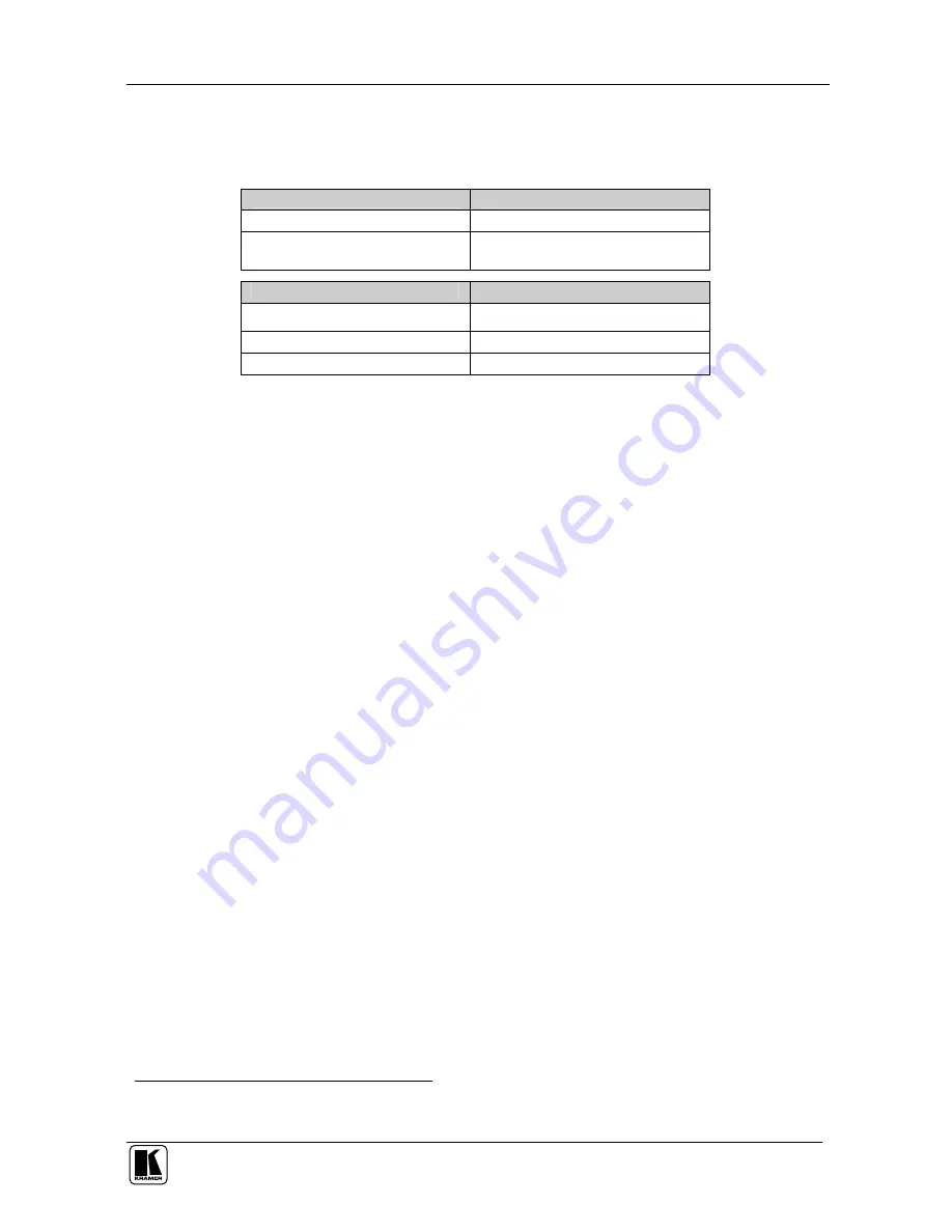
Table 2 is valid as per January 2004. Newer machines (using Protocol 2000) 

may be programmed for Group 12 or 11. 

Table 4: Group Definition Criteria for Older Machines 

Group 

Speed

1


1, 2, and 3 

1200 

4, 5, 6, 7, 9, 10 12, 14, 15, 16, 17, 

18 and 20 

9600 


Group 

Maximum # of Units per Group 

Groups 7

2

, 9 and 10 

1


Groups 1, 2, 3, 5, 6, 15, 17, and 18 

8


Groups 4, 12, 14, and 16 

16


7.3  Using the RC-IR2 keys in the ROUTER Mode 

The following sections describe how to: 


Use the <-> and <--> keys for selecting the single or the double digit 

modes (see section 7.3.1) 


Switch an input to an output (see section 7.3.2) 


Use the STO and RCL keys for storing and recalling switcher settings (see 

section 7.3.3) 


Use the TAKE key (see section 7.3.4) 


Use the VIDEO AUDIO and AFV keys (see section 7.3.5) 

7.3.1 

The <0/10> Selector Key 

The <0/10> key represents either 0 or 10 depending on the digit mode: 


When the single-digit mode is selected, by pressing the <-> key, the 

selector button <0/10> represents 10 (in the sequence from 1 to 20) 


When the double-digit mode is selected, by pressing the <--> key, the 

selector button <0/10> represents 0 (in a sequence from 01 to 99) 

For example, to select 5 in the single-digit mode, press <5> and when in the 

double-digit mode, press <0/10> and <5>. 


1 Baud (with no parity, 8 data bits and 1 stop bit) 
2 One video unit and one audio unit 

Содержание RC-IR2

Страница 1: ...Kramer Electronics Ltd USER MANUAL Model RC IR2 Infrared Remote Control Device Remote Control Transmitter Remote Receiver...

Страница 2: ...TO and RCL Keys 12 7 3 3 1 Storing an Input Output Configuration 12 7 3 3 2 Recalling an Input Output Configuration 12 7 3 4 The TAKE Key 13 7 3 4 1 Confirming a Switching Action 13 7 3 5 The VIDEO AU...

Страница 3: ...ns 16 Tables Table 1 RC IR2 Remote Control Transmitter Features 4 Table 2 RC IR2 Initializing Sequence 9 Table 3 Group Definition Specifications for Older Machines 10 Table 4 Group Definition Criteria...

Страница 4: ...ceiver use4 an external remote receiver5 2 Getting Started We recommend that you Unpack the equipment carefully and save the original box and packaging materials for possible future shipment Review th...

Страница 5: ...rrupted To achieve the best performance Point the remote control transmitter directly at the remote receiver whether built in or external Make sure that nothing blocks the path of the infrared beam2 C...

Страница 6: ...Control Transmitter Figure 1 and Table 1 define the RC IR2 remote control transmitter POWER Cycles power Button colors key The red LED lights when sending instructions Routers Switchers General WHITE...

Страница 7: ...Aspect Ratios Normal Wide Screen Pan Scan 4 3 Output and 16 9 Output Navigation Control 5 keys Allows maneuvering within an OSD screen all keys adjusts the zoom position 4 keys moves the PIP location...

Страница 8: ...el remote receiver you can use the external remote receiver1 see Figure 3 The external remote receiver includes an attached RS 232 cable with a 9 pin D sub connector and a 12V DC power socket Caution...

Страница 9: ...tached RS 232 cable s 9 pin D sub connector and the RS 232 9 pin D sub port on the switcher A cross connection or Null modem adapter when required For the cross connection connect PIN 2 to PIN 3 PIN 3...

Страница 10: ...necessitate restarting that action 6 The General Gray Keys The RC IR2 includes a power ON button a red transmission LED which illuminates when pressing any key as well as Selector buttons which operat...

Страница 11: ...6 17 18 and 20 there are no groups numbered 8 13 or 19 Groups numbered 1 2 3 4 14 15 and 16 include units with only a single output In some cases you will need to allocate different versions of the sa...

Страница 12: ...hine number to the RC IR2 do the following 1 Point the remote control transmitter at the remote receiver and press the ROUTER key 2 Press the digit corresponding to the machine number2 This sets and s...

Страница 13: ...4228 VS 1604 SD 7316 SD 7388 VP 88 VP 84 VP 82 VP 66 VP 64 VS 1602xl VS 1202xl VS 1002xl VS 804YC VS 806YC VS 808xl VS 606xl VS 646 VS 402 VS 602 VS 401xlm VS 601xlm VS 801xlm VS 1001xl VS 1201xl VS...

Страница 14: ...input to an output see section 7 3 2 Use the STO and RCL keys for storing and recalling switcher settings see section 7 3 3 Use the TAKE key see section 7 3 4 Use the VIDEO AUDIO and AFV keys see sect...

Страница 15: ...t Configuration To store the current status in memory do the following 1 Press the STO key 2 Press one of the Selector keys this will be the setup in which the current status is stored The memory stor...

Страница 16: ...y to confirm and implement the action 7 3 5 The VIDEO AUDIO and AFV Keys You can switch stereo audio signals in one of two ways either Audio follow video AFV in which all operations relate to both the...

Страница 17: ...see section 7 4 1 1 Adjust the volume see section 7 4 1 2 7 4 1 1 Switching an Input to an Output The VP 23N Presentation Switcher includes three independent switchers and one Master audio switcher Ea...

Страница 18: ...e of the VP 23N You can increase and or decrease the volume2 of the VP 23N using the RC IR2 remote control transmitter Increasing the Volume of the VP 23N The volume level on the VP 23N Presentation S...

Страница 19: ...il the volume decrease is satisfactory 7 4 2 Controlling the VP 26 via the RC IR2 You can control the VP 26 Presentation Switcher using the RC IR2 to do the following Switch inputs to outputs see sect...

Страница 20: ...ntrol transmitter at the remote receiver and do the following 1 Press the AUDIO key 2 Press 1 and then press any key according to the audio output type key in Table 8 to switch an input to the Master...

Страница 21: ...key defining the audio signal3 continuously until the volume decrease is satisfactory 7 5 Controlling an Expanded Series 16x16 Matrix Switcher You can control an expanded series 16x16 matrix switcher...

Страница 22: ...1 to 5 you can use the selector buttons from 1 to 18 to select the source 8 1 The Volume keys in the SCALER Mode Use the VOL and VOL keys to increase or decrease the volume For the VP 725DS and VP 725...

Страница 23: ...ghtning orotheractsofnature ii Product modification orfailureto followinstructions supplied with theproduct iii Repairorattemptedrepairby anyonenotauthorized byKramer iv Anyshipmentofthe product claim...

Страница 24: ...or the latest information on our products and a list of Kramer distributors visit our Web site www kramerelectronics com where updates to this user manual may be found We welcome your questions commen...

Отзывы: