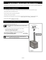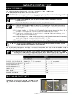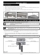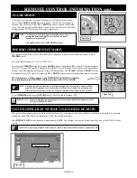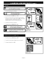
1. Remove screen front and glass frame assembly from fireplace.
2. Align leg section holes to corresponding mounting nuts in mounting brackets on sides of
fireplace opening. Secure with phillips truss head screws (2 ea. side).
3. Re-install glass frame assembly and screen front.
PAGE 17
VENT SYSTEM CONNECTION
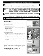
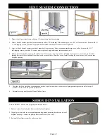
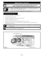
1. Place air duct (previously removed, page 15) into existing fireplace opening.
2.
Place a bead of sealant (provided) around exhaust collar („EX‟ marking) Slide exhaust pipe over „EX‟ collar on air duct. Secu
re with (3)
½" self-tapping screws, provided. Apply additional sealant around joint to ensure an air tight seal.
3. Apply a liberal bead of sealant (provided) around collar on air duct. Slide combustion intake pipe over collar. Secure with (3) ½"
self-tapping screws, provided. To ensure an air-tight seal, apply additional sealant around joint.
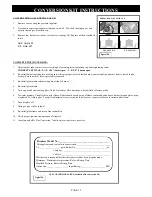
4. Slide insert into fireplace opening. Check for level. If necessary, leveling bolts are included in components packet and are threaded
through bottom of insert into nuts located on each corner of insert. Remove insert, install leveling legs as necessary, slide insert into
fireplace opening.
5. Use glass latch tool included in components packet, to pull air duct down onto insert, aligning mounting studs to holes in top of
firebox. Secure with nuts previously removed.
6. Reinstall access panel plate, baffle and firebox liners.
Sheet metal
screws (3 total)
Sealant
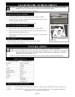
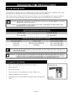
This kit includes: Shroud and (4) phillips truss head screws.
SHROUD INSTALLATION
Figure 17d
Figure 17a
Figure 17c
Figure 17b
Figure 17e
Содержание MPS-34 Minneapolis XL
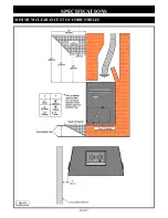
Страница 8: ...SPECIFICATIONS PAGE 7 MINIMUM CLEARANCES TO COMBUSTIBLES Figure 7a...
Страница 37: ...PAGE 36 LIMITED WARRANTY...
Страница 38: ...PAGE 37 LIFETIME WARRANTY...

