6. Product Description
CB 752 – User's Guide (Version 1.01)
6.1.2.
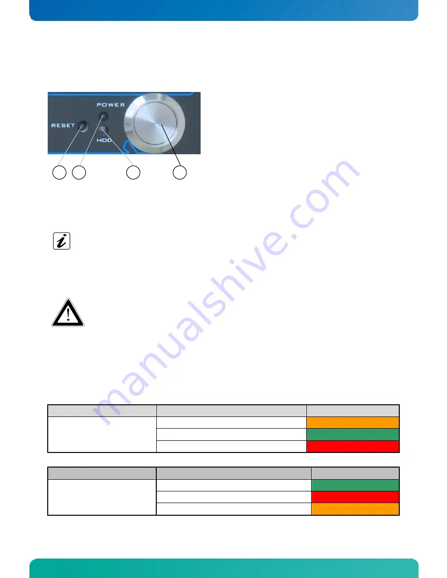
Controls and Indicators
1
2
3
4
Power button
3
HDD activity LED
2
Power LED
1
RESET button
4
Fig. 10: CB 752 –Controls and Indicators
6.1.2.1.
Power Button
Press this button (Fig. 10, pos. 4) to switch the system on or off.
Please note the BIOS setup settings (BIOS Setup / Chipset / South Bridge Configuration / Restore on AC
Power Loss, setup options:
Power On
/ Power Off). “Power On” is the default setting.
Please also note the description in chapter 10.2 “Protection against Overheating”.
Prerequisite:
The CB 752 has to be connected to an appropriate main power supply (DC or AC via AC/DC adapter).
Even when the system is turned off via the power button there is still a standby-voltage of 5 VSb on the
SBC.
Switching the system off using the power button does not disconnect the device from the mains. The unit
is only completely disconnected from the mains, when the power cord is disconnected either from the
mains or the unit. Therefore, the power cord and its connectors must always remain easily accessible.
6.1.2.2.
Power LED and HDD LED
The power LED (Fig. 10, pos. 2) and the HDD LED (Fig. 10, pos. 3) which are located on the front side of the CB 752
platform indicate the system status.
System
System Status
Color of the Power LED
The system is in standby mode
orange
The system is operational.
green
CB 752
(The DC IN connector is connected
to the main power supply.)
Voltage, temperature or battery error
red
Activity of the installed Storage Media
Color of the HDD LED
CF card only
green
SATA HDD or SATA-SSD only
red
CB 752
(The DC IN connector is connected
to the main power supply.)
CF card and SATA HDD/SATA SSD simultaneously
orange
12
www.kontron.com


