background image

9. Menu

Field Service 

V

er. 1.0 Apr. 200

8

122

bizhub C31P

Adjustment / Setting

D. Counter Information

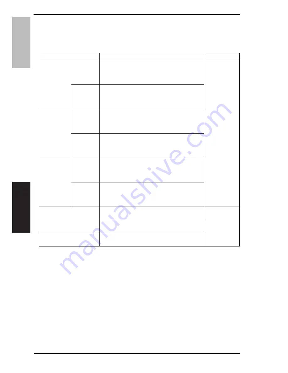
• The total number of pages that have been printed is counted and displayed based on the 

description shown in the following table.

<Counter information list>

*1: A count of 100 in the counter is converted to 1 sheet of media and display the number of 

decimals are discarded.

NOTE
• The total counters and the print counters count at a different timing, when a sheet 

of media is properly ejected and when a sheet of media is fed, respectively.
Therefore, the sum of each total counter value may not be same with the sum of 
each print counter value if a sheet of media cannot be ejected due to media jam 
inside the machine or other possible problems.

Types of count

Contents

Count timing

Total Count

Monochrome

• The total number of monochrome pages ejected 

from the printer.
Increment by one per simplex and by two per 
duplex

When a sheet of 
media is ejected 

properly

Full color

• The total number of color pages ejected from the 

printer. 
Increment by one per simplex and by two per 
duplex

Total Count 

(duplex)

Monochrome

• The total number of monochrome duplex sheets 

ejected from the printer. 
Increment by one per duplex (and by zero per sim-
plex)

Full color

• The total number of color duplex sheets ejected 

from the printer. 
Increment by one per duplex (and by zero per sim-
plex)

Total Count 

(Normalized)

Monochrome

• The total number of monochrome pages on a A4 

basis that have been ejected from the printer. 
Increment by 100 per A4 simplex and by 200 per 
A4 duplex *1

Full color

• The total number of color pages on a A4 basis that 

have been ejected from the printer. 
Increment by 100 per A4 simplex and by 200 per 
A4 duplex *1

Sheets Printed by Paper Tray

• The number of sheets used for each media source. 

Increment by one for both simplex and duplex

When a sheet of 

media is fed

Sheets Printed by Paper Size

• The number of sheets used for each media size. 

Increment by one for both simplex and duplex

Sheets Printed by Paper Type

• The number of pages used per each media type. 

Increment by one for both simplex and duplex

Содержание Bizhub-C31P

Страница 1: ...SERVICE MANUAL 2008 04 2008 04 Ver 1 0 Ver 1 0 FIELD SERVICE ...

Страница 2: ...RES TO TAKE IN CASE OF AN ACCIDENT S 21 Composition of the service manual C 1 Notation of the service manual C 2 bizhub C31P Main body General 1 Maintenance 5 Adjustment Setting 93 Troubleshooting 195 Appendix 239 Lower feeder unit General 1 Maintenance 3 Adjustment Setting 13 Troubleshooting 15 Duplex option General 1 Maintenance 3 Troubleshooting 9 Staple finisher General 1 Maintenance 5 Trouble...

Страница 3: ...ii Blank Page ...

Страница 4: ...rse of technical training and even after that for performing maintenance and control of the product properly Keep this service manual also for future service In this service manual each of three expressions DANGER WARNING and CAUTION is defined as follows together with a symbol mark to be used in a limited meaning When servicing the product the relevant works disassembling reassembling adjustment ...

Страница 5: ...erformance and safety Such modifications are therefore strictly prohibited the points listed below are not exhaustive but they illustrate the reason ing behind this policy SAFETY WARNINGS Prohibited Actions DANGER Using any cables or power cord not specified by KMBT Using any fuse or thermostat not specified by KMBT Safety will not be assured leading to a risk of fire and injury Disabling fuse fun...

Страница 6: ...cable having enough cur rent capacity and the cord set meets regulatory requirements for the area Use of inadequate cord set leads to fire or electric shock Attach power plug which meets the following criteria having configuration intended for the connection to wall outlet appropriate for the product s rated voltage and current and the plug has pin terminal s for grounding and meets regulatory req...

Страница 7: ...er leads to the product connecting to inadequate power supply voltage current capacity grounding and may result in fire or electric shock If proper wall outlet is not available advice the customer to contact qualified electrician for the installation Plug the power cord into the dedicated wall outlet with a capacity greater than the maximum power consumption If excessive current flows in the wall ...

Страница 8: ...o a risk of fire Check whether the power cord is damaged Check whether the sheath is damaged If the power plug cord or sheath is damaged replace with a new power cord with plug and connector on each end specified by KMBT Using the damaged power cord may result in fire or electric shock Do not bundle or tie the power cord Overheating may occur there leading to a risk of fire Check whether dust is c...

Страница 9: ...not use an extension cable reel with the cable taken up Fire may result Prohibited Installation Places WARNING Do not place the product near flammable materials or vola tile materials that may catch fire A risk of fire exists Do not place the product in a place exposed to water such as rain A risk of fire and electric shock exists When not Using the Product for a long time WARNING When the product...

Страница 10: ...e Servicing CAUTION Before conducting an inspection read all relevant docu mentation service manual technical notices etc and proceed with the inspection following the prescribed pro cedure in safety clothes using only the prescribed tools Do not make any adjustment not described in the docu mentation If the prescribed procedure or tool is not used the prod uct may break and a risk of injury or fi...

Страница 11: ... risk of elec tric shock exists Safety Checkpoints WARNING Check the exterior and frame for edges burrs and other damage The user or CE may be injured Do not allow any metal parts such as clips staples and screws to fall into the product They can short internal circuits and cause electric shock or fire Check wiring for squeezing and any other damage Current can leak leading to a risk of electric s...

Страница 12: ...ng a lithium battery replace it with a new lith ium battery specified in the Parts Guide Manual Dispose of the used lithium battery using the method specified by local authority Improper replacement can cause explosion After replacing a part to which AC voltage is applied e g optical lamp and fixing lamp be sure to check the installa tion state A risk of fire exists Check the interlock switch and ...

Страница 13: ... breathe excessive amounts or let the substances come into contact with eyes etc It may be stimulative If the substances get in the eye rinse with plenty of water immediately When symptoms are noticeable consult a physician Never throw the used cartridge and toner into fire You may be burned due to dust explosion Handling of Service Materials CAUTION Unplug the power cord from the wall outlet Drum...

Страница 14: ...eaner at a time and take care not to spill any liquid If this happens immediately wipe it off A risk of fire exists When using any solvent ventilate the room well Breathing large quantities of organic solvents can lead to discomfort Handling of Service Materials CAUTION ...

Страница 15: ...ar le constructeur Mettre au rebut les batteries usagées conformément aux instructions du fabricant Denmark ADVARSEL Lithiumbatteri Eksplosionsfare ved fejlagtig håndtering Udskiftning må kun ske med batteri af samme fabrikat og type Levér det brugte batteri tilbage til leverandøren Finland Sweden VAROlTUS Paristo voi räjähtää jos se on virheellisesti asennettu Vaihda paristo ainoastaan laitevalmi...

Страница 16: ...e of the Print Head Unit This product employs a Class 3B laser diode that emits an invisible laser beam The laser diode and the scanning polygon mirror are incorporated in the print head unit The print head unit is NOT A FIELD SERVICEABLE ITEM Therefore the print head unit should not be opened under any circumstances semiconductor laser Maximum power of the laser diode 15 mW Maximum average radiat...

Страница 17: ...nd must be attached to laser products marketed in the United States All Areas Denmark CAUTION Use of controls adjustments or performance of procedures other than those specified in this manual may result in hazardous radiation exposure semiconductor laser Maximum power of the laser diode 15 mW Wavelength 770 800 nm CAUTION Use of controls adjustments or performance of procedures other than those s...

Страница 18: ... användaren utsättas för osynlig laserstrålning som överskrider gränsen för laserklass 1 halvledarlaser Den maximala effekten för laserdioden 15 mW våglängden 770 800 nm VARO Avattaessa ja suojalukitus ohitettaessa olet alttiina näkymättomälle laser säteilylle Älä katso säteeseen VARNING Osynlig laserstråining när denna del är öppnad och spärren är urkopplad Betrakta ej stråien ADVERSEL Dersom app...

Страница 19: ...S S 16 5 2 Laser Safety Label A laser safety label is attached to the inside of the machine as shown below 5 3 Laser Caution Label A laser caution label is attached to the outside of the machine as shown below A011P0E504DA A011P0C503DA ...

Страница 20: ...nd PC drum be sure first to turn the printer OFF If the job requires that the printer be left ON take off your watch and ring and wear laser protective goggles A highly reflective tool can be dangerous if it is brought into the laser beam path Use utmost care when handling tools on the user s premises The Print Head is not to be disassembled or adjusted in the field Replace the Unit or Assembly in...

Страница 21: ... special care should be taken to avoid burns and electric shock WARNING INDICATIONS ON THE MACHINE A011P0C505DA High voltage This area generates high voltage Be careful not to touch here when the power is turned ON to avoid getting an electric shock CAUTION The area around the Fusing Unit is extremely hot Touching any part other than those indicated may result in burns ...

Страница 22: ...e This area generates high voltage Be careful not to touch here when the power is turned ON to avoid getting an elec tric shock High voltage This area generates high voltage Be careful not to touch here when the power is turned ON to avoid getting an elec tric shock ...

Страница 23: ...Toner Bottle Toner expelled from the fire is dangerous WARNING Do not burn used Toner Cartridge Toner expelled from the fire is dangerous You may be burned or injured if you touch any area that you are advised not to touch by any caution label Do not remove caution labels If any caution label has come off or soiled and therefore the caution cannot be read contact our Service Office ...

Страница 24: ...of a serious accident has been received from a customer an on site evalua tion must be carried out quickly and KMBT must be notified 3 To determine the cause of the accident conditions and materials must be recorded through direct on site checks in accordance with instructions issued by KMBT 4 For reports and measures concerning serious accidents follow the regulations speci fied by every distribu...

Страница 25: ...MEASURES TO TAKE IN CASE OF AN ACCIDENT S 22 Blank Page ...

Страница 26: ...formation The basic configuration of each section is as follows However some options may not be applied to the following configuration Theory of Operation section Field service section OUTLINE Explanation of system configuration product specifications unit configuration and paper path COMPOSITION OPERATION Explanation of configuration of each unit operating system and control system GENERAL Explan...

Страница 27: ...ng will be identified with S abbreviation for Short edge feeding on the paper size No specific notation is added for the long edge feeding When the size has only the short edge feeding with no long edge feeding S will not be added to the paper size Sample notation 1 bizhub C31P Main body 2 Microsoft Windows NT 4 0 Windows NT 4 0 or Windows NT Microsoft Windows 2000 Windows 2000 Microsoft Windows X...

Страница 28: ...SERVICE MANUAL 2008 04 Ver 1 0 FIELD SERVICE Main body ...

Страница 29: ...f times the revision has been made To indicate clearly a specific page that contains a revision or revisions the page number appear ing at the left or right bottom of the specific page is marked with The number inside represents the number of times the revision has been made NOTE Revision marks shown in a page are restricted only to the latest ones with the old ones deleted When a page revised in ...

Страница 30: ...feed roller 9 3 4 2 Replacing the tray 1 feed roller 10 3 4 3 Replacing the ozone filter 13 3 4 4 Replacing the toner cartridge C M Y K 13 3 4 5 Replacing the imaging unit C M Y K 16 3 4 6 Replacing the waste toner bottle 20 3 4 7 Replacing the transfer roller 21 3 4 8 Replacing the transfer belt 22 3 4 9 Replacing the fuser unit 24 4 Service tool 25 4 1 CE tool list 25 4 2 Consumable parts 25 4 2...

Страница 31: ...rear cover 49 6 3 8 Tray 2 50 6 3 9 Tray 1 50 6 3 10 Operation board OB 51 6 3 11 Hard disk kit option 52 6 3 12 MFP board MFPB 53 6 3 13 Print control board PRCB 55 6 3 14 DC power supply DCPU 57 6 3 15 High voltage unit 1 HV1 59 6 3 16 High voltage unit 2 HV2 60 6 3 17 Toner level sensor board TLSB 61 6 3 18 PH Unit 64 6 3 19 Driving unit 71 6 3 20 MFP board fan motor FM5 72 6 3 21 Backup batter...

Страница 32: ...section 93 8 Description of the control panel 94 8 1 Control panel display 94 8 1 1 Parts of the control panel display 94 8 1 2 Message structure 95 8 1 3 Normal messages 96 8 1 4 Operator call messages 101 8 1 5 Service call messages 102 8 1 6 Help screen 103 8 2 List of control panel messages 104 8 2 1 Normal messages 104 8 2 2 Operator call messages 107 8 2 3 Service call messages 110 8 3 Cance...

Страница 33: ...PCL SETTING 134 9 5 9 PS SETTING 136 9 5 10 CALIBRATION 140 9 5 11 COLOR SEPARATION 141 9 6 MEMORY DIRECT 142 9 6 1 LIST OF FILES 142 9 6 2 TYPE OF FILES 142 9 7 CAMERA DIRECT 142 9 7 1 PAPER SOURCE 142 9 7 2 LAYOUT 143 9 7 3 PAPER MARGIN 143 9 7 4 IMAGE QUALITY 143 9 8 INTERFACE MENU 145 9 8 1 JOB TIMEOUT 145 9 8 2 ETHERNET 146 9 8 3 MEMORY DIRECT 153 9 8 4 CAMERA DIRECT 153 9 9 SYS DEFAULT MENU ...

Страница 34: ...10 4 SUPPLIES 177 9 10 5 QUICK SETTING 177 10 Adjustment item list 179 11 SERVICE MENU 180 11 1 How to enter the service menu 180 11 2 Service menu function tree 181 11 3 SERVICE MENU 182 11 3 1 SERIAL NUMBER 182 11 3 2 FIRMWARE VERSION 182 11 3 3 ALIGNMENT 182 11 3 4 DIAGNOSIS MENU 186 11 3 5 SUPPLIES 189 11 3 6 RESTORE PASSWARD 190 11 3 7 BK CLEAR 190 11 3 8 QUICK SETTING 191 11 3 9 FIRMWARE UPD...

Страница 35: ...ction 208 14 3 6 004C Ozone ventilation fan motor malfunction 208 14 3 7 004E DC power supply fan motor malfunction 209 14 3 8 0060 Fusing motor malfunction 209 14 3 9 0094 2nd image transfer pressure retraction failure 210 14 3 10 0096 1st image transfer pressure retraction failure 211 14 3 11 0300 Polygon motor malfunction 211 14 3 12 0310 Laser malfunction 212 14 3 13 0500 Heating roller warm u...

Страница 36: ...9 C060 Firmware update error 217 14 3 40 C071 Hardware configuration error 218 14 3 41 FFFF Interface communication error 218 15 Power supply troubles 219 15 1 Machine is not energized at all DCPU operation check 219 15 2 Control panel indicators do not light 219 15 3 Fusing heaters do not operate 220 16 Image quality problems 221 16 1 Solution 221 16 1 1 White lines bands colored lines bands in s...

Страница 37: ... 16 Back marking 236 16 1 17 Uneven pitch 237 16 1 18 No print cycles can be run as commanded via the network 238 Appendix 17 Parts layout drawing 239 17 1 Main body 239 17 2 Lower feeder unit option 242 17 3 Duplex option option 243 17 4 Staple finisher option 244 18 Connector layout drawing 247 19 Timing chart 248 ...

Страница 38: ...2008 1 System configuration 1 bizhub C31P General General 1 System configuration System front view 1 bizhub C31P 4 Lower feeder unit 2 Duplex option 5 Lower feeder unit 3 Hard disk kit 6 Staple finisher A011F1C501DA 4 5 6 2 1 3 ...

Страница 39: ...rge neutralizing system Fusing system Belt fusing Media exit system Face down Output tray capacity A4S LetterS 250 sheets Warm up time Average 52 sec or less Sleep mode to ready at ambient temperature of 23 C 73 4 F and rated source voltage Process speed 216 mm sec plain paper full color mode First page out time 14 0 second Full color mode A4S LetterS 1 sided mode plain paper Print speed 37 0 page...

Страница 40: ...ches Tray 2 Plain paper 60 to 90 g m2 16 to 24 lb Recycled paper 60 to 90 g m2 16 to 24 lb Tray capacities Tray 1 Manual tray Plain paper and recycled paper 100 sheets Thick stock 1 thick stock 2 glossy paper 1 glossy paper 2 OHP film letterhead labels postcards and double postcards 20 sheets Envelopes 10 sheets Long size paper 1 sheet No indication of remaining media amount Tray 2 Plain paper and...

Страница 41: ... 10 only US Canada AC 220 to 240 V 10 10 Frequency 50 to 60 Hz 3 Hz Max power consumption 1 450 W or less Dimensions 420 mm W x 526 mm D x 420 mm H 16 5 inch W x 20 7 inch D x 16 5 inch H Weight 33 4 kg 73 6 lb or less without consumables Operating noise During standby 39 dB A or less During printing 56 dB A or less Temperature 10º to 35º C 50º to 95º F with a fluctuation of 10º C 18º F or less pe...

Страница 42: ... toner cartridge C M Y K 12 000 Continuous printing 2 Imaging unit C M Y K 30 000 Continuous printing 3 Ozone filter 4 120 000 4 Tray 2 media feed section Feed roller When malfunction occurs 5 Tray 1 media feed section Feed roller When malfunction occurs 6 Image transfer section Transfer belt unit 120 000 Continuous printing 2P J 1 7 Transfer roller 4 120 000 Continuous printing 2P J 1 8 Waste ton...

Страница 43: ...eplacement parts A Main body 1 2 pages job 2 120 V areas only 3 230 V areas only B Option 1 For details see the optional lower feeder unit service manual No Class Maintenance parts Quan tity Actual durable cycle Parts No Descrip tion Ref page 1 Tray 2 media feed section Feed roller 1 300 000 4138 3032 P 9 2 Tray 1 media feed section Feed roller 1 300 000 4138 3032 P 10 3 Fusing section Fuser unit ...

Страница 44: ...ns 104 000 prints 120 000 prints for continuous printing 130 000 prints 150 000 prints for continuous printing Ozone filter 120 000 prints Transfer roller The life is detected based on the number of pages printed The consumption rate is calculated from the number of pages printed and the machine detects the life when the consumption rate reaches the value corresponding to the life value shown on t...

Страница 45: ...ber of pages printed or figures equivalent to it when the given conditions see the table given below are met They may be more or less depending on the machine operating conditions of each individual user Item Description Job type 2 consecutive pages 2 pages job PV M 1 800 Media size A4S or LetterS Color ratio Black to Color 1 1 Original density C W ratio 5 each color ...

Страница 46: ...4 1 Replacing the tray 2 feed roller A Periodically replacing parts cycle Tray 2 feed roller Every 300 000 prints B Procedure 1 Slide out tray 2 2 Lock the media lift plate 1 3 Snap off two C rings 2 and remove the bearing 3 at the front 4 Snap off the C ring 1 and remove the feed roller 2 A0EAF2C001DA 1 2 2 3 1 2 A011F2C002DA ...

Страница 47: ... the direction shown in the illustration on the left 3 4 2 Replacing the tray 1 feed roller A Periodically replacing parts cycle Tray 1 feed roller Every 300 000 prints B Procedure 1 Open the tray 1 2 Remove the tray 1 cover 3 Disconnect the connector 1 4 Move two lock levers 1 up 5 Remove the tray 1 2 A011F2C501DA 1 A0EAF2C002DA 1 A0EAF2C003DA 1 2 ...

Страница 48: ...two pins 1 in and lift the feed roller cover 2 upward to remove it NOTE Make sure that the bearing goes all the way into both of 1 shown on the left when installing the feed roller cover 7 Remove the two screws 1 and remove the cover 2 A0EAF2C004DA 2 1 1 A011F2C502DA 1 A0EAF2C005DA 1 2 ...

Страница 49: ...1 and remove the bearing 2 at the front 9 Snap off the C ring 1 and remove the clutch 2 and the feed roller 3 NOTE When reinstalling the feed roller 1 and the clutch make sure that it is mounted in the direction shown in the illustration on the left A0EAF2C006DA 1 2 A0EAF2C007DA 1 3 2 A011F2C503DA 1 ...

Страница 50: ... ter 1 and slide it out of the machine 2 Install a new ozone filter in the machine 3 Replace the transfer roller See P 21 3 4 4 Replacing the toner cartridge C M Y K A Periodically replacing parts cycle Standard capacity toner cartridge C M Y K Every 6 000 prints High capacity toner cartridge C M Y K Every 12 000 prints B Removal procedure 1 Open the front door 2 Slide the lock lever 1 to the righ...

Страница 51: ...1 to unlock the toner cartridge 4 Grasp the toner cartridge handle 1 and pull the toner cartridge 2 out C Reinstallation procedure 1 Take the toner cartridge out of its plastic bag 2 Gently shake the toner cartridge 1 three times to agitate the toner Y 1 A011F2C506DA Y Y 2 1 A011F2C507DA Y 1 A011F2C508DA ...

Страница 52: ...odical check 15 bizhub C31P Maintenance 3 Grasp the toner cartridge handle 1 and slide the toner cartridge 2 in 4 Remove the protective sheet by pull ing it 5 Raise the lock lever 1 Y Y 2 1 A011F2C509DA Y Y 1 A011F2C510DA Y 1 A011F2C511DA ...

Страница 53: ...toner cartridge while it is being used or after it has been used up do not hold it or place it upside down as spilled toner could result 3 4 5 Replacing the imaging unit C M Y K A Periodically replacing parts cycle Imaging unit C M Y K Every 30 000 prints continuous 20 000 prints 2 pages job B Removal procedure 1 Open the front door 2 Slide the lock lever 1 to the right Y 1 A011F2C512DA K 1 A011F2...

Страница 54: ...nlock the imaging unit 4 Press down the Push marked place 1 5 Pull the imaging unit 2 out C Reinstallation procedure 1 After removing the plastic bag hold the imaging unit 1 with your hands and shake it two times as shown in the left illustration K 1 A011F2C514DA 2 A011F2C515DB 1 Y PUSH Y PU SH 1 1 A011F2C516DB ...

Страница 55: ...Service Ver 1 0 Apr 2008 18 bizhub C31P Maintenance 2 Remove the shipping tape of the imaging unit 1 3 Remove the protective cover 1 4 Slide the imaging unit 1 in K P U S H 1 A011F2C517DA K P U S H 1 A011F2C518DB 1 A011F2C519DA ...

Страница 56: ...nce 5 Raise the lock lever 1 6 Slide the lock lever 1 to the left to lock the imaging unit 7 Close the front door NOTE When installing and removing the imaging unit take care not to touch the surface of the PC drum 1 K 1 A011F2C520DA K 1 A011F2C521DA Y P U S H 1 A011F2C522DA ...

Страница 57: ...acing parts cycle Waste toner bottle Every 36 000 prints black print only 9 000 prints color print only B Procedure 1 Open the front door 2 Turn the lever 1 to unlock the waste toner bottle 3 Holding the left and right handles 1 remove the waste toner bottle 2 4 To reinstall reverse the order of removal 1 A011F2C523DA 2 1 A011F2C524DA ...

Страница 58: ...nds of the transfer roller 1 inward to unlock the transfer roller 1 3 Holding the levers remove the trans fer roller 1 4 To reinstall reverse the order of removal 5 Replace the ozone filter See P 13 6 From the Menu select SERVICE MENU SUPPLIES REPLACE TRANS ROLLER and execute this function to reset the transfer roller counter value See P 190 7 From the Menu select QUALITY MENU CARIBRATION AIDC PRO...

Страница 59: ...000 prints B Procedure 1 Turn OFF the power switch 2 Open the front door 3 Remove the imaging units C M Y K See P 16 4 Remove the waste toner bottle See P 20 5 Remove four screws 1 and remove the left cover 2 6 Open the right door 7 Loosen two screws 1 and unlock the transfer belt 8 Slide the shutter lever 1 to the front A0EAF2C008DA 1 2 1 A011F2C528DA 1 1 A011F2C529DA 1 ...

Страница 60: ...elt 2 along the rails 1 NOTE When inserting the unit use care not to allow the docking gear to hit against the rail or other mechanism to prevent damage 12 To reinstall reverse the order of removal 13 From the Menu select SERVICE MENU SUPPLIES REPLACE TRANS BELT and execute this function to reset the transfer belt counter value See P 189 14 From the Menu select QUALITY MENU CALIBRATION AIDC PROCES...

Страница 61: ...board See P 51 4 Remove the upper front cover See P 46 5 Disconnect five connectors 1 6 Remove two screws 1 and remove the fuser unit 2 7 Install the new fuser unit 8 From the Menu select SERVICE MENU SUPPLIES REPLACE FUSER UNIT and execute this function to reset the fuser unit counter value See P 190 CAUTION The temperature gets high in the vicinity of the fuser unit You may get burned when you c...

Страница 62: ...18 1 10pcs 1pack Isopropyl alcohol Laser lens cleaning tool A011 1901 A02EF2C526DA A00KF2C506DA A011F2C544DA Part name Life expectancy High capacity toner cartridge black K 12 000 prints High capacity toner cartridge yellow Y 12 000 prints High capacity toner cartridge magenta M 12 000 prints High capacity toner cartridge cyan C 12 000 prints Part name Life expectancy Black imaging unit 30 000 pri...

Страница 63: ...l Field Service Ver 1 0 Apr 2008 26 bizhub C31P Maintenance 4 2 3 Waste toner bottle For the predetermined conditions See P 8 Part name Life expectancy Waste toner bottle Monochrome 36 000 prints Color 9 000 prints ...

Страница 64: ...ystem requirements PC equipped with a USB port USB memory device B Saving the firmware data into the USB memory device 1 Save the firmware data in appropriate space in the PC 2 Connect the USB memory device to the PC 3 Create a firmware folder immediately under the drive of the USB memory device 4 Copy the firmware data exe in the firmware folder created in step 3 NOTE Be sure to save the firmware...

Страница 65: ... A list of firmware data in the USB memory device is displayed NOTE Before upgrading firmware use VIEW INFORMATION to check that the firmware data is correct See P 192 5 Select the specific firmware data to be upgraded and press the Menu Select key 6 Select EXECUTE and press the Menu Select key 7 Select YES and press the Menu Select key A0DXF2E535DA FIRMWARE UPDATE EXIT file name 1 file name 2 A0D...

Страница 66: ...ESSING DON T REMOVE MEMORY Computer Windows PC with a Pentium 2 400 MHz or faster processor A Pentium 3 500 MHz or faster processor is recommended Macintosh Apple Macintosh computer with a PowerPC G3 or later proces sor A PowerPC G4 or later is recommended OS Windows Microsoft Windows XP Home Edition Professional Windows 2000 Macintosh MacOS X 10 2 or later We recommend installing the newest patch...

Страница 67: ...E Before starting the firmware updater turn on the printer and make sure that it is correctly connected 1 Download the firmware updater 2 Double click xxxxxxxxxxxx exe 3 The printer name and firmware version are displayed Click the Next 4 The license agreement is displayed Select I agree and then click the Next A011F2E555DA A011F2E556DA ...

Страница 68: ... For a network connection Select Network port See P 32 For a local connection Select Local port See P 35 When specifying the IP address of the printer Select Printer IP address See P 36 NOTE If you select Network port or Local port make sure that the printer driver has been installed If you select Printer IP address the firmware can be updated even if a printer driver is not already installed A011...

Страница 69: ...selected a list of printer drivers for the network port appears 2 Select the printer driver and then click the Next 3 A message appears requesting confirmation to update the firmware Click the Start to begin transferring the firmware NOTE Do not turn off the printer while its firmware is being updated A011F2E558DA A011F2E559DA ...

Страница 70: ...1 0 Apr 2008 5 Firmware upgrade 33 bizhub C31P Maintenance 4 The result of the firmware transfer is displayed Click the Exit 5 If the firmware was successfully updated the printer will automatically restart A011F2E560DA ...

Страница 71: ...fails NOTE If spooling fails data may remain in the printer spooler Delete this data and then try again 1 If spooling of the data fails the following message appears 2 Click OK 3 Check that the printer is ready and that it is correctly connected and then click the Update again A011F2E561DA A011F2E562DA ...

Страница 72: ...elected a list of printer drivers for the local port appears 2 Select the printer driver and then click the Next 3 A message appears requesting confirmation to update the firmware Click the Start to begin transferring the firmware NOTE Do not turn off the printer while its firmware is being updated A011F2E563DA A011F2E564DA ...

Страница 73: ...rmware was successfully updated the printer will automatically restart If spooling of the data fails For details see For a network connection See P 34 4 When specifying the IP address of the printer 1 When Printer IP address is selected the Printer IP address box becomes available 2 Type in the IP address and then click the Next A011F2E565DA A011F2E566DA ...

Страница 74: ...on to update the firmware Click the Start to begin transferring the firmware NOTE Do not turn off the printer while its firmware is being updated 4 The result of the firmware transfer is displayed Click the Exit 5 If the firmware was successfully updated the printer will automatically restart A011F2E567DA A011F2E565DA ...

Страница 75: ...hub C31P Maintenance If transferring of the data fails 1 If transferring of the data fails the following message appears 2 Click OK 3 Check that the printer is ready and that it is correctly connected and then click the Update again A011F2E569DA A011F2E570DA ...

Страница 76: ...ing procedure NOTE Before starting the firmware updater turn on the printer and make sure that it is correctly connected 1 Download the firmware updater 2 Double click xxxxxxxxxxxx 3 The printer name and firmware version are displayed Click the Next 4 The license agreement is displayed Select I agree and then click the Next A011F2E571DA A011F2E572DA ...

Страница 77: ... IP address of the printer appears 6 Type in the IP address and then click the Next 7 A message appears requesting confirmation to update the firmware Click the Start to begin transferring the firmware NOTE Do not turn off the printer while its firmware is being updated A011F2E573DA A011F2E574DA A011F2E575DA ...

Страница 78: ... Exit 9 If the firmware was successfully updated the printer will automatically restart If transferring of the data fails 1 If transferring of the data fails the following message appears 2 Click OK 3 Check that the printer is ready and that it is correctly connected and then click the Update again A011F2E576DA A011F2E577DA A011F2E578DA ...

Страница 79: ...P Maintenance 5 3 2 Checking the version after the firmware update 1 Display SERVICE MENU 2 Display FIRMWARE VERSION 3 Select the firmware that has been updated and check the current version See P 182 A011F2E545DA FIRMWARE VERSION CONTROLLER F W ENGINE F W BOOT F W ...

Страница 80: ...in order to prevent them from being removed by mistake Do not remove or loosen any of the red painted screws in the field It should also be noted that when two or more screws are used for a single part only one repre sentative screw may be marked with the red paint C Variable resistors on board NOTE Do not turn the variable resistors on boards for which no adjusting instructions are given in Adjus...

Страница 81: ...High voltage unit 1 HV1 P 59 16 High voltage unit 2 HV2 P 60 17 Toner level sensor board TLSB P 61 18 Units PH Unit P 64 19 Driving unit P 71 20 Other Parts MFP board fan motor FM5 P 72 21 Backup battery P 73 22 PWB box 1 P 74 23 PWB box 2 P 75 24 Color PC drum motor M2 P 75 25 Intermediate transport motor M3 P 78 26 Fusing motor M4 P 77 27 Developing motor K M5 P 76 28 Toner supply motor Y M M6 P...

Страница 82: ...e Ver 1 0 Apr 2008 6 Other 45 bizhub C31P Maintenance 6 2 2 Cleaning parts list No Section Part name Ref Page 1 Tray 1 Feed roller P 91 2 Tray 2 Feed roller P 91 3 Processing section Laser irradiation section P 92 ...

Страница 83: ... 1 Front door 1 Open the front door 2 Remove the E ring 1 3 Slide the front door 2 to the left off the machine 6 3 2 Upper front cover 1 Open the front door 2 Open the right door 3 Remove the operation board See P 51 4 Remove the screw 1 and remove the upper front cover 2 2 1 A011F2C553DA A0EAF2C011DA 1 2 ...

Страница 84: ...over See P 46 3 Remove the screw 1 and remove the right front cover 2 6 3 4 Left cover 1 Open the front door 2 Remove four screws 1 3 Remove the left cover 1 NOTE Remove the left cover as shown in the illustration on the left taking care not to damage three tabs 2 on the upper edge of the left cover A0EAF2C012DA 1 2 A0EAF2C013DA 1 1 A0EAF2C014DA 2 1 ...

Страница 85: ...ear cover 2 in the direc tion shown in the illustration on the left off the machine 6 3 6 Exit tray 1 Open the front door 2 Remove the operation board See P 51 3 Remove the upper front cover See P 46 4 Remove the left cover See P 47 5 Remove the rear cover See P 48 6 Remove two covers 1 A011F2C535DA 2 1 A0EAF2C015DA 1 ...

Страница 86: ...C31P Maintenance 7 Remove two screws 1 8 Remove the screw 1 and remove the exit tray 2 6 3 7 Right rear cover 1 Open the right door 2 Remove the rear cover See P 48 3 Open the cover and remove the screw 1 A0EAF2C016DA 1 A0EAF2C017DA 1 2 A0EAF2C018DA 1 ...

Страница 87: ...k three tabs and remove the right rear cover 1 6 3 8 Tray 2 1 Slide out the tray 2 1 2 Pressing the tabs 2 on both sides remove the tray 2 1 6 3 9 Tray 1 1 Open the tray 1 2 Remove the tray 1 cover 3 Disconnect the connector 1 A0EAF2C019DA 1 A0EAF2C020DA 2 2 1 A0EAF2C002DA 1 ...

Страница 88: ... 4 Move two lock levers 1 up 5 Remove the tray 1 2 6 3 10 Operation board OB 1 Open the front door 2 Remove the left cover See P 47 3 Remove three screws 1 and remove the operation board 2 4 Disconnect two connectors 1 A0EAF2C003DA 1 2 A0EAF2C023DA 1 2 A0EAF2C024DA 1 ...

Страница 89: ... 11 Hard disk kit option 1 Remove the rear cover See P 48 2 Loosen seven screws 1 and remove the MFP board protective shield 2 3 Remove three mounting pins 1 4 Disconnect the connector 1 and remove the hard disk kit 2 A011F2C536DB 1 2 1 1 A0EAF2C025DA 1 A0EAF2C026DA 1 2 ...

Страница 90: ...trol panel again See P 153 1 Remove the rear cover See P 48 2 Loosen seven screws 1 and remove the MFP board protective shield 2 3 Remove the MFP board fan motor See P 72 4 Remove the left cover See P 47 5 Remove seven screws 1 6 Disconnect three connectors 1 on the MFP board 7 Disconnect two flat cables 2 from the MFP board A011F2C536DB 1 2 1 1 A0EAF2C027DA 1 1 A0EAF2C028DA 2 1 ...

Страница 91: ... board 11 Remove the backup battery from the MFP board See P 73 NOTE When the MFP board is replaced upgrade the firmware to the latest version See P 27 NOTE After the replacement of the MFP board you need to rewrite new security data into the hard disk and the compact flash if you would like to continue to use the data that has been stored in these disks See P 193 A0EAF2C029DA 1 1 2 1 2 A011F2C024...

Страница 92: ...over See P 48 2 Remove the right rear cover See P 49 3 Remove seven screws 1 and remove the MFP board protective shield 2 4 Remove six screws 1 and the print control board protective shield 2 5 Disconnect all connectors and flat cables from the print control board 1 A011F2C536DB 1 2 1 1 A0EAF2C030DA 1 2 A0EAF2C031DA 1 ...

Страница 93: ...from the print control board NOTE When the print control board PRCB has been replaced be sure to remount parameter chip IC4 Unmount parameter chip IC4 from the old print control board and mount it on the new print control board NOTE When mounting parameter chip IC4 make sure the notches A are precisely lined up A0EAF2C032DA 1 1 2 1 A011F2C029DB A0EAF2C502DA ...

Страница 94: ... See P 47 3 Remove the operation board See P 51 4 Remove the upper front cover See P 46 5 Remove the exit tray See P 48 6 Loosen seven screws 1 and remove the MFP board protective shield 2 7 Disconnect two connectors 1 on the MFP board 8 Remove the screw 1 9 Remove the cable from the wire sad dle 2 A011F2C536DB 1 2 1 1 A0EAF2C033DA 1 A0EAF2C034DA 1 2 ...

Страница 95: ... bizhub C31P Maintenance 10 Remove five screws 1 and the DC power supply protective cover 2 11 Disconnect all connectors on the DC power supply 12 Remove eight screws 1 and the DC power supply 2 A0EAF2C035DA 1 2 A0EAF2C036DA A0EAF2C037DA 1 1 2 ...

Страница 96: ...See P 74 2 Disconnect the harness 1 and two flat cables 2 from the harness plate 3 3 Remove the harness from three wire saddles 4 4 Remove three screws 1 and remove the harness plate 2 5 Remove two screws 1 twelve springs 2 and the high voltage unit 1 assy 3 A0EAF2C038DA 2 2 4 1 3 A0EAF2C039DA 1 2 1 3 2 A011F2C035DA ...

Страница 97: ...e flat cable 2 7 Remove the high voltage unit 1 3 6 3 16 High voltage unit 2 HV2 1 Remove the high voltage unit 1 See P 59 2 Disconnect all connectors and flat cables from the high voltage unit 2 1 3 Remove two screws 1 and remove the high voltage unit 2 2 1 2 3 A011F2C036DA 1 A011F2C037DA 2 1 A011F2C038DA ...

Страница 98: ... removed from the main body be sure to place it in the plastic bag black or wrap it in a light shielding cloth and store it in a dark place Do not leave the imaging unit exposed to light for a extended period of time as it may become damaged 4 Remove the waste toner bottle See P 20 5 Remove the upper front cover See P 46 6 Remove the right front cover See P 47 7 Remove the operation board See P 51...

Страница 99: ...nce 10 Disconnect the connector PJ13A 1 from the print control board 11 Remove the harness from the har ness plate 1 and four wire saddles 2 12 Remove seven screws 1 and remove the toner level sensor board assy 2 A0EAF2C040DA 1 A0EAF2C041DA 2 1 A0EAF2C042DA 1 2 1 ...

Страница 100: ...Field Service Ver 1 0 Apr 2008 6 Other 63 bizhub C31P Maintenance 13 Remove three screws 1 14 Disconnect two connectors 1 and remove the toner level sensor board 2 A0EAF2C043DA 1 A0EAF2C044DA 1 2 ...

Страница 101: ...a dark place Do not leave the imaging unit exposed to light for a extended period of time as it may become damaged 4 Remove the waste toner bottle See P 20 5 Remove the transfer belt See P 22 6 Remove the left cover See P 47 7 Remove the print control board protective shield See the steps 1 to 4 on P 55 Print control board 8 Disconnect the connector PJ22A 1 and the flat cable PJ23A 2 from the prin...

Страница 102: ...saddle 4 16 Remove the screw 1 and remove the drawing up transportation assy 2 NOTE Waste toner may spill out from the waste toner inlet of the drawing up transportation assy Take care not to tilt the waste toner inlet when removing the drawing up transportation assy 2 The draw ing up transportation assy 2 also needs to be placed in a horizontal position where no waste toner will spill out A0EAF2C...

Страница 103: ...intenance 17 Remove four screws 1 and remove corresponding four imaging unit rails 2 18 Remove three shoulder screws 1 of the PH unit 19 Pull the connector 1 and the flat cable 2 out and remove the PH unit 3 A0EAF2C047DA 1 2 1 A011F2C048DA 3 1 2 A011F2C049DA ...

Страница 104: ...rt the PH unit connector 1 and flat cable 2 from the positions shown in the left illustration Then route them to the rear direc tion 4 Install the PH unit 1 into the main body NOTE After the PH unit installation check that the shield sheet is grounded properly onto the base of the PH unit Make sure that the shield sheet does not have any unnecessary crease positional misalignment nor loose attachm...

Страница 105: ...5 Fix the PH unit 2 with three shoul der screws 1 6 Attach the four imaging unit rails 2 with one screw 1 for each rail NOTE Make sure that the convex parts 3 at rear end of the rail are fit in the locating hole 4 on the main body 1 2 A011F2C053DA A0EAF2C048DA 1 2 3 4 ...

Страница 106: ...that the rear gear 1 keeps its own rectangular slot 2 vertically long 2 Turn the connecting part 1 so that it becomes vertically long 3 Insert the drawing up transporta tion assy shaft 1 into the rear mounting hole 2 4 Insert the connecting part 3 of the drawing up transportation assy into the rear gear slot 4 1 2 3 A011F2C054DA 1 A011F2C055DA 1 2 4 3 A011F2C056DA ...

Страница 107: ...tion assy are engaged Use a 0 1 mm piece of a thickness gauge to check the gap between the positioning protrusion 1 and the main body frame Make sure that the piece of the thickness gauge cannot pass through the gap A transparency can replace the thickness gauge Check that the shield sheet which confirmed in step 4 is well grounded onto PH unit base plate at malt of drawing up transportation assy ...

Страница 108: ...ee P 77 7 Remove the intermediate transport motor See P 78 8 Remove the media feed and transport assy See the steps 1 to 6 on P 82 Media feed clutch 1 9 Disconnect the connector 1 10 Remove the harness from two wire saddles 2 11 Remove seven screws 1 and remove the driving assy 2 NOTE When installing the driving unit assy 2 take care not to damage or soil the gears 12 Remove the pressure retractio...

Страница 109: ...aintenance 6 3 20 MFP board fan motor FM5 1 Remove the rear cover See P 48 2 Loosen seven screws 1 and remove the MFP board protective shield 2 3 Remove four screws 1 connector 2 and remove the MFP board fan motor 3 A011F2C536DB 1 2 1 1 A0EAF2C051DA 2 1 1 3 ...

Страница 110: ... your backup battery replacement refer to the section of Removal of PWBs on P 43 When working with printed boards hold the boards only by the edges 1 Remove the rear cover See P 48 2 Loosen seven screws 1 and remove the MFP board protective shield 2 3 Press the backup battery 1 in the way shown in the picture on the left and remove it from the housing 4 Insert a new backup battery 1 NOTE When inse...

Страница 111: ... C31P Maintenance 6 3 22 PWB box 1 1 Remove the MFP board See P 53 2 Remove the print control board See P 55 3 Remove the exit tray See P 48 4 Remove seven screws 1 5 Remove the harness 1 and remove the PWB box 1 2 1 1 1 A011F2C061DA 1 2 A011F2C062DA ...

Страница 112: ...the PWB box 1 See P 74 4 Remove nine screws 1 and remove the PWB box 2 2 6 3 24 Color PC drum motor M2 1 Remove the PWB box 1 See P 74 2 Disconnect the connector 1 and remove three screws 2 and the color PC drum motor 3 NOTE When installing the color PC drum motor 3 try to insert it straight and take care not to damage the gears 1 1 2 A011F2C063DA 1 2 3 A011F2C064DB ...

Страница 113: ...OTE When installing the developing motor K 3 try to insert it straight and take care not to damage the gears 6 3 26 Toner supply motor Y M M6 1 Remove the PWB box 1 See P 74 2 Disconnect the connector 1 and remove two screws 2 and the toner supply motor Y M 3 NOTE When installing the toner supply motor Y M 3 try to insert it straight and take care not to dam age the gears 1 2 3 A011F2C065DA 1 3 2 ...

Страница 114: ...OTE When installing the toner supply motor C K 3 try to insert it straight and take care not to dam age the gears 6 3 28 Fusing motor M4 1 Remove the PWB box 1 See P 74 2 Remove the PWB box 2 See P 75 3 Disconnect the connector 1 and remove four screws 2 and the fus ing motor 3 NOTE When installing the fusing motor 3 try to insert it straight and take care not to damage the gears 1 2 3 A011F2C067D...

Страница 115: ...connector 1 and remove four screws 2 and the intermediate transport motor 3 NOTE When installing the intermediate transport motor 3 try to insert it straight and take care not to dam age the gears 6 3 30 Registration roller clutch CL2 1 Open the right door 2 Unhook the tab 1 and remove the connector cover 2 3 Disconnect the connector 1 1 3 2 A011F2C069DA A0EAF2C055DA 1 2 A0EAF2C056DA 1 ...

Страница 116: ...re that the notch 3 on the regis tration roller clutch comes to the position shown in the left picture 5 Remove the registration roller clutch 1 6 3 31 Pressure retraction clutch 2 CL5 1 Open the front door 2 Remove the right front cover See P 47 3 Open the right door 4 Remove five screws 1 and remove the connector cover 2 A0EAF2C057DA 1 2 3 A0EAF2C058DA 1 A0EAF2C059DA 1 1 2 ...

Страница 117: ...r Field Service Ver 1 0 Apr 2008 80 bizhub C31P Maintenance 5 Disconnect eight connectors 6 Remove the door sensor Fr PS14 1 7 Remove the gear 1 1 and the gear 2 2 A011F2C075DB 1 A011F2C076DA 1 2 A011F2C077DA ...

Страница 118: ...utch 2 3 NOTE When reinstalling the bearing and pressure retraction clutch 2 make sure that the protrusion 4 on the pressure retraction clutch 2 fits into the locking slot 5 6 3 32 Pressure retraction clutch 1 CL4 1 Remove the driving unit assy See P 71 2 Remove three screws 1 3 Snap off two E rings 2 4 Remove two bearings 3 and the pressure retraction clutch 1 assy 4 1 2 A011F2C078DA 1 2 3 5 4 A0...

Страница 119: ...ling the bearing and pressure retraction clutch 1 make sure that the protrusion 1 on the pressure retraction clutch 1 fits into the locking slot 2 6 3 33 Media feed clutch 1 CL1 1 Remove the PWB box 1 See P 74 2 Remove the PWB box 2 See P 75 3 Disconnect the white connector 1 and the blue connector 2 1 2 A011F2C081DA A0EAF2C060DA 1 2 A0EAF2C061DA 1 2 ...

Страница 120: ...eed clutch 1 is reinstalled replace the gears that have been removed as these gears could have been damaged 6 Remove the media feed and trans port assy 3 7 Snap off the E ring 1 8 Remove the bearing 2 and spring 3 NOTE Fit the E ring 1 to the lower groove 4 of the two grooves in the shaft A0EAF2C062DA 1 1 A0EAF2C063DA 1 3 2 A011F2C086DC 1 2 3 4 ...

Страница 121: ...ance 9 Snap off the E ring 1 and remove the bearing 2 10 Snap off the E ring 1 and remove the bearing 2 11 Remove four screws 1 12 Remove the media feed and trans port assy holding metal plate 2 and the shaft 3 1 2 A011F2C087DB 1 2 A011F2C088DB 1 2 3 A011F2C090DB ...

Страница 122: ...he media feed clutch 1 1 NOTE When reinstalling the media feed clutch 1 make sure that the protru sion 1 on the media feed clutch fits into the locking slot 2 Pass the harness of the media feed clutch through the location shown in the picture on the left 1 A011F2C091DB 1 A011F2C092DB 1 2 A011F2C093DB ...

Страница 123: ...See P 75 3 Disconnect the white connector 1 and the blue connector 2 4 Remove four screws 2 5 Remove the gear 1 and the gear 2 NOTE When the media feed clutch 2 is reinstalled replace the gears that have been removed as these gears could have been damaged 6 Remove the media feed and trans port assy 3 A0EAF2C061DA 1 2 A0EAF2C062DA 1 1 A0EAF2C063DA 1 3 2 ...

Страница 124: ...1 8 Remove the bearing 2 and spring 3 NOTE When reinstalling the E ring 1 fit it to the lower groove 4 of the two grooves in the shaft 9 Snap off the E ring 1 and remove the bearing 2 10 Snap off two E rings 1 and remove two bearings 2 A011F2C086DC 1 2 3 4 1 2 A011F2C087DB 1 2 A011F2C094DB ...

Страница 125: ... Maintenance 11 Remove four screws 1 12 Remove the media feed and trans port assy holding metal plate 2 and the shaft 3 13 Remove three gears 1 14 Remove the shaft 1 and remove the media feed clutch 2 2 1 2 3 A011F2C090DB 1 1 A011F2C095DB 2 1 A011F2C096DB ...

Страница 126: ...the media feed clutch 2 fits into the locking slot 2 6 3 35 Temperature humidity sensor TEM HUMS 1 Open the right door 2 Remove the screw 2 from the sen sor holder 1 3 Remove the sensor holder 1 by sliding it to the front 4 Remove the screw 1 disconnect the connector 2 and remove the temperature humidity sensor 1 2 A011F2C097DA A0EAF2C064DA 1 2 A0EAF2C065DA 1 2 ...

Страница 127: ...n the right door 2 Remove the transfer belt See P 22 3 Remove two screws 1 4 Unhook the spring and remove the cover 1 NOTE Be careful not to lose the spring 5 Disconnect one connector 1 each 6 Remove two screws 2 each and remove the IDC sensor board Fr 3 and IDC sensor board Re 4 A0EAF2C066DA 1 A0EAF2C067DA 1 A0EAF2C068DA 1 1 3 4 2 2 ...

Страница 128: ... 1 feed roller 1 Open the tray 1 2 Press down on the center of the media lifting plate 1 until the left and right locking tabs lock into place 3 Using a cleaning pad dampened with alcohol wipe the feed roller 1 clean of dirt 6 4 2 Tray 2 feed roller 1 Slide out tray 2 2 Using a cleaning pad dampened with alcohol wipe the feed roller 1 clean of dirt 1 A0EAF2C501DA 1 A011F2C548DA A011F2C539DA 1 ...

Страница 129: ...or 2 Align the edge of the laser lens cleaning tool 2 with the marker 1 at four places of the waste toner bottle Insert the tool 2 and make two to three reciprocating motions to clean the laser irradiation section NOTE For cleaning do not use any tool other than the specified laser lens cleaning tool A011F2C540DA 1 2 ...

Страница 130: ...tric noise 4 The installation site is environmentally appropriate high temperature high humidity direct sunlight ventilation etc levelness of the installation site 5 The original has a problem that may cause a defective image 6 The density is properly selected 7 Correct media is being used for printing 8 The units parts and supplies used for printing developer PC drum etc are properly replenished ...

Страница 131: ...vided into LCD 1 LCD 2 LCD 3 and LCD 4 LCD 4 may display a message instructing you to press a key on the control panel When you press that key the displayed message changes NOTE The display screen is not designed for touch panel operation therefore do not touch the icons on the screen If it is pushed too hard the LCD liquid crystal dis play may be damaged A011F3E504DA Cancel Menu Select Ready Erro...

Страница 132: ...ages These messages are displayed when minor error s that can be handled by users occur Service call messages These messages are displayed when error s that cannot be handled by users occur Help messages These messages are displayed when the down key T is pressed when a nor mal message warning or operator call message is displayed Normal message Menu message Operator call message Service call mess...

Страница 133: ...unt is not determined immediately after startup When using toner made by companies other than KMBT Display Description LCD 1 Printer mode is displayed Normally READY is displayed LCD 2 The message is displayed Normally no message is displayed LCD 3 LCD 4 Key guidance is displayed Normally MENU to enter is displayed When the MENU key is pressed the panel displays the MENU screen When a WARNING mess...

Страница 134: ...2 Job information is displayed for example 1 AKIRA KUROSAWA The job owner name etc set with PJL commands is displayed When multiple jobs are set the number is displayed to the left of the owner name LCD 3 Job progress is displayed for example 1 7 page In normal print mode Number of processed print Total number of print is displayed When printing in sets Number of processed print Total number of a ...

Страница 135: ...YSTEM Controller firmware BOOT Boot firmware RESOURCE Resource file CONFIGURATION Equipment configuration file ENGINE Engine firmware LCD 3 Progress of the update is displayed for example 90 LCD 4 No display A0EAF3E503DA FIRMWARE UPDATE YMCK SYSTEM 90 Firmware update Type of firmware Progress Display Description LCD 1 Print mode is displayed and warning icon is displayed on the right for example R...

Страница 136: ...ing the MENU key the selected item is entered By pressing the Cancel key the job cancel menu is closed By selecting CURRENT JOB or ALL JOB and pressing the MENU key job cancellation is implemented Display Description LCD 1 CANCEL JOB is displayed LCD 2 CONTINUE is displayed Function Continue the print of currently processing job LCD 3 CURRENT JOB is displayed Function Stop the print of currently p...

Страница 137: ...enu See P 113 Display Description LCD 1 A Warning icon is displayed LCD 2 Menu items are displayed 3 items 7 items By pressing the up keyS down keyT the item is selected The menu consists of the following 8 items PROOF PRINT MENU PRINT MENU PAPER MENU QUALITY MENU MEMORY DIRECT CAMERA DIRECT INTERFACE MENU SYS DEFAULT MENU MAINTENANCE MENU SERVICE MENU LCD 3 LCD 4 A0EAF3E507DA MENU PROOF PRINT MEN...

Страница 138: ...s displayed and the gauge of the appropriate color flashes for example the M gauge In the case of an operator call message for another reason the printer icon is displayed with a flashing warning icon For the details of each item see Operator call messages See P 107 Display Description LCD 1 A warning icon is displayed and the state is displayed on the right for example TONER EMPTY LCD 2 Message i...

Страница 139: ...call A printer icon is displayed with a flashing warning icon A service call detected during startup of the printer is displayed as shown in the bottom of the following picture For the details of each item see Service call messages See P 110 Display Description LCD 1 A Warning icon is displayed and the service call message and a 4 digit service call ID are displayed on the right for example SERVIC...

Страница 140: ...D 1 A Question icon is displayed and the necessary information is displayed on the right for example PREPARE NEW WASTE TONER BOTTLE LCD 2 LCD 3 LCD 4 A scroll bar or S to exit message is displayed If there are several messages a scroll bar is displayed By pressing the left keyW right keyX a previous next screen message is displayed If all messages are displayed S to exit displays on the screen A0E...

Страница 141: ...oo See P 119 8 2 1 Normal messages A Normal messages Message LCD1 Description INITIALIZING The printer is being initialized READY Print enabled Data not being printed OFFLINE Off line condition Data reception not available TELNET allows offline setting ENERGY SAVER Machine in energy saver mode PROCESSING Print data processing Data receiving printer is started PRINTING Data being printed Printer is...

Страница 142: ...IT END OF LIFE Fuser unit service life has been reached 11 STAPLER EMPTY 1 The staple finisher has run out of staples Otherwise the staples are almost empty 12 WASTE TONER NEAR FULL The waste toner bottle needs replacement soon 13 I UNIT LOW X The specified color imaging unit will run out soon This message appears when SYS DEFAULT MENU ENABLE WARN ING I UNIT LOW is set to ON 14 TONER LOW X The spe...

Страница 143: ...he optional staple finisher is mounted 22 DEVICE NOT SUPPORTED An unsupported device is connected to the USB host I F 23 AUTH TIMEOUT Time out of the IEEE 802 1X port authentication processing Low 24 PORT AUTH ACTIVE IEEE 802 1X port authentication processing is being executed Priority Message LCD2 LCD3 Description ...

Страница 144: ...e model By pressing the right key different messages appear one after another During the display of the messages key operations other than the right key are disabled In the last message screen the machine can recover from the error by pressing the Menu Select key How ever the same message appears when the power switch is turned OFF and ON the printer is being rebooted or the printer covers are bei...

Страница 145: ...t match that of the media loaded in the specified tray Load SSSS size media in the specified tray 12 TRAYX TYPE ERROR ADD TTTT 2 The media size set in the printer driver does not match that of the media loaded in the specified tray Load TTTT type media in the specified tray 13 ADJUST TRAY1 Tray 1 manual feed tray is removed from the printer 14 STAPLER EMPTY REPLACE STAPLE CARTRIDGE The staples are...

Страница 146: ...n the specified tray at media feeding Displays when TRAY CHAINING is set to OFF 18 OUTPUT FULL REMOVE PAPER The printed media volume has reached maximum capacity in the exit tray of the main body REMOVE PAPER SUB TRAY 1 The printed media volume has reached maximum capacity in the sub tray of the staple finisher REMOVE PAPER MAIN TRAY 1 The printed media volume has reached maximum capacity in the m...

Страница 147: ...failure 0510 FUSER ERROR Abnormally low heating roller temperature 0511 FUSER ERROR Abnormally low fusing pressure roller temperature 0520 FUSER ERROR Abnormally high heating roller temperature 0521 FUSER ERROR Abnormally high fusing pressure roller temperature 0B30 FINISHER ERROR Finisher aligning plate drive malfunction 0B47 FINISHER ERROR Finisher media holding drive malfunction 0B48 FINISHER E...

Страница 148: ...t startup C025 CONTROLLER ROM Controller ROM error Configuration information error C026 Controller ROM error Access error C027 Controller ROM error Data error C050 HDD ERROR HDD access error C051 HDD DISK FULL HDD full error 1 C052 CARD ERROR Compact flash access error C053 CARD FULL Compact flash full error 1 C060 UPDATE ERROR Firmware update error C071 H W CONFIGURA TION ERROR Hardware configura...

Страница 149: ...rinted a message appears on the control panel 2 Select the job to be cancelled using the up keyS down keyT and press the MENU SELECT key By pressing the Cancel key the job cancel menu is closed Panel Display LCD2 LCD4 Description CONTINUE Continue printing the currently processing job CURRENT JOB Stop printing the currently processing job ALL JOB Stop printing all jobs including the currently proc...

Страница 150: ...AY 2 P 128 TRAY 3 P 128 TRAY 4 TRAY CHAINING P 129 TRAY MAPPING P 129 DUPLEX 2 P 129 COPIES P 130 COLLATE 4 P 130 FINISHING 5 P 130 JOB SEPARATION 5 P 131 IMAGE ROTATION 3 P 131 QUALITY MENU COLOR MODE P 131 BRIGHTNESS P 131 HALFTONE IMAGE PRINTING P 132 TEXT PRINTING P 132 GRAPHICS PRINTING P 132 EDGE ENHANCE MENT IMAGE PRINTING P 132 TEXT PRINTING P 133 GRAPHICS PRINTING P 133 EDGE STRENGTH P 13...

Страница 151: ...PROF P 138 GRAPHICS PRINTING RGB SOURCE P 138 RGB INTENT P 139 RGB GRAY P 139 DESTINATION PROF P 139 SIMULATION SIMULATION PROF P 139 SIMULATION INTENT P 140 CMYK GRAY P 140 CALIBRATION TONE CALIBRATION P 140 AIDC PROCESS P 140 CMYK DENSITY CYAN P 140 MAGENTA P 141 YELLOW P 141 BLACK P 141 COLOR SEPARATION P 141 MEMORY DIRECT 1 6 LIST OF FILES 7 P 142 TYPE OF FILES P 142 CAMERA DIRECT 8 PAPER SOUR...

Страница 152: ...LNET P 148 BONJOUR ENABLE P 148 DYNAMIC DNS ENABLE P 148 IPP ENABLE P 149 RAW PORT ENABLE P 149 BIDIRECTIONAL SLP ENABLE P 149 SMTP ENABLE P 149 SNMP ENABLE P 150 WSD PRINT ENABLE P 150 IPSEC ENABLE P 150 IP ADDRESS FILTER ACCESS PREMISSION P 150 ACCESS REFUSE IPv6 ENABLE P 151 AUTO SETTING LINK LOCAL GLOBAL ADDRESS GATEWAY ADDRESS NETWARE ENABLE P 152 APPLETALK ENABLE P 152 SPEED DUPLEX P 152 IEE...

Страница 153: ...156 PAPER DEFAULT PAPER PAPER SIZE P 156 CUSTOM SIZE P 157 PAPER TYPE P 157 UNIT OF MEASURE P 157 GRAYSCALE PAGE P 158 STARTUP OPTIONS DO STARTUP PAGE P 158 AUTO CONTINUE P 158 HOLD JOB TIMEOUT 1 P 158 ENERGY SAVER P 159 ENERGY SAVER TIME 9 P 159 MENU TIMEOUT P 159 LCD CONTRAST P 159 SECURITY CHANGE PASSWORD P 160 LOCK PANEL P 160 CLOCK DATE xx xx xx P 161 TIME P 161 TIME ZONE P 161 HDD FORMAT 1 P...

Страница 154: ... the flash memory is not connected or not recognized 8 It will be displayed only when the following setting is set to ENABLE INTERFACE MENU CAMERA DIRECT 9 It will be displayed when ENERGY SAVER is set to either of the options other than OFF 10 It will be displayed only when a compact flash is installed 11 It will be displayed only when a USB memory device is installed MAINTENANCE MENU PRINT MENU ...

Страница 155: ...e hold job is set as secured job the held job cannot be printed until the correct password is entered at the printer control panel The held job is deleted automatically after the period of time specified in the SYSTEM DEFAULT MENU HOLD JOB TIMEOUT menu How to delete the held job 1 Select PROOF PRINT MENU and press the Menu Select key 2 Select user name and press the Menu Select key 3 Select desire...

Страница 156: ... machine The following items can be checked Supplies Status PM Parts Information Counter Information Media Information Coverage Information Consumable periodic replacement parts units counter information 1 1 For details see the following table How to read consumable periodic replace ment parts units counter information Setting procedure Select PRINT and press the Menu Select key ...

Страница 157: ...lor Average 23 2 Total Monochrome Monochrome Average 4 9 Current Toner Cartridge Average C Average M Average Y Average K 3 3 0 6 2 2 9 6 3 3 0 6 2 2 9 6 Total Average C Average M Average Y Average K LEGAL LETTER A4 B5 JIS A5 CUSTOM OTHERS 0 1 18 0 0 0 0 PLAIN PAPER RECYCLED THICK 1 THICK 2 LABEL TRANSPARENCY ENVELOPE POSTCARD LETTER HEAD GLOSSY 1 GLOSSY 2 19 0 0 0 0 0 0 0 0 0 0 Sheets Printed by P...

Страница 158: ...lay the status of the waste toner bottle and the staple unit NOTE The percent of life remaining in the toner cartridge or imaging unit can be used as a guide but may not exactly reflect the amount that has been used in the toner cartridge or imaging unit C PM Parts Information Display the estimated percent of life remaining in periodic replacement parts and units such as the transfer roller transf...

Страница 159: ...roperly Full color The total number of color pages ejected from the printer Increment by one per simplex and by two per duplex Total Count duplex Monochrome The total number of monochrome duplex sheets ejected from the printer Increment by one per duplex and by zero per sim plex Full color The total number of color duplex sheets ejected from the printer Increment by one per duplex and by zero per ...

Страница 160: ...he average of the ratios of dot space on each page when the print able area is defined as 100 and shown in 0 1 percent increments Normalized Coverage Information Total Individual average dot coverage of four colors Y M C K is calculated on an A4 basis for all prints performed after the printer was installed The average of the ratios of dot space on each page when the print able area is defined as ...

Страница 161: ...MBT has been replaced 10 Number of times a high capacity toner cartridge Y has been replaced 11 Not used 12 Number of times a toner cartridge Y made by companies other than KMBT has been replaced 13 Use of counterfeit toner cartridge K is set at 1 The default value is 0 14 Use of counterfeit toner cartridge C is set at 1 The default value is 0 15 Use of counterfeit toner cartridge M is set at 1 Th...

Страница 162: ... a postscript font list Use To determine which postscript fonts are available on the printer Setting procedure Select PRINT and press the Menu Select key Function Prints a PCL font list Use To determine which PCL fonts are available on the printer Setting procedure Select PRINT and press the Menu Select key Function Prints a menu map Use To see the printer s menu structure Setting procedure Select...

Страница 163: ...e media in tray 1 Use To specify the size of the media loaded in tray 1 Setting procedure 1 Select PAPER SIZE and press the Menu Select key 2 Select desired paper size and press the Menu Select key For North America The default setting is LETTER For other destinations The default setting is A4 ANY LETTER LEGAL EXECUTIVE A4 A5 A6 B5 JIS B6 JIS GOVT LETTER STATE MENT FOLIO SP FOLIO UK QUARTO FOOLSCA...

Страница 164: ...lt setting of LENGTH is 11 00 inches LENGTH 5 83 inches to 14 00 inches For other destinations The default setting of WIDTH is 210 mm WIDTH 92 mm to 216 mm The default setting of LENGTH is 297 mm LENGTH 148 mm to 356 mm NOTE By changing the UNIT OF MEASURE setting INCHES MILLIMETERS the custom size units are changed Function Sets the media type for tray 1 Use To specify the type of media loaded in...

Страница 165: ... 2 Select desired paper type and press Menu Select key The default setting is PLAIN PAPER ANY PLAIN PAPER RECYCLED NOTE ANY identifies any media type Function Automatically detects the set paper size and displays it Use To check the paper size Setting procedure 1 Select PAPER SOURCE and press the Menu Select key 2 Select desired feed tray TRAY 3 4 and press the Menu Select key 3 Select PAPER SIZE ...

Страница 166: ...r s printer driver are printed using tray 1 to tray 4 Use To specify the media source for print jobs using another manufacturer s printer driver Setting procedure Only the default for LOGICAL TRAY 1 is PHYSICAL TRAY 1 PHYSICAL TRAY 2 is the default for all trays other than LOGICAL TRAY 1 PHYSICAL TRAY 1 PHYSICAL TRAY 2 PHYSICAL TRAY 3 PHYSICAL TRAY 4 NOTE Only the mounted tray can be selected Func...

Страница 167: ...r driver overrides the setting in this menu Function Selects an exit tray and finishing option at the staple finisher Use To select an exit tray and finishing option when a optional staple finisher is installed SUB TRAY Printing to the sub tray MAIN TRAY Printing to the main tray OFFSET The media is fed to the main tray with each copy slightly shifted STAPLING Each copy is stapled and fed to the m...

Страница 168: ...media sizes Media type Plain Recycled Letterhead paper Paper size 182 to 216 mm in width and 257 to 356 mm in length Function Prints 180 degrees rotated images Use To exit the leading edge of a printed image first during printing when an optional sta ple finisher is not installed Setting procedure The default setting is OFF ON OFF NOTE This menu is available only when an optional staple finisher i...

Страница 169: ...sizes the resolution of the print image DETAIL HALFTONE characteristic that emphasizes the balance between the resolution and the tone reproducibility of the print image SMOOTH HALFTONE characteristic that emphasizes the tone reproducibility of the print image Setting procedure The default setting is LINE ART LINE ART DETAIL SMOOTH Function Sets the halftone characteristic for graphics printing Us...

Страница 170: ... ON ON OFF Function Sets edge strength applied to printing with edge enhancement Use To adjust edge strength depending on each image In the order of Low Middle and High edge strength increases Setting procedure The default setting is MIDDLE OFF LOW MIDDLE HIGH NOTE If this setting is set to OFF the EDGE ENHANCEMENT setting is disabled and jobs print without edge enhancement Function Selects whethe...

Страница 171: ... printed image Setting procedure The default setting is 0 15 10 5 0 5 10 15 Function Sets the RGB color space of the image to be printed Use To set the input RGB color space that is used for printing the image picture sRGB Profile that has been preset to the printer DEVICE COLOR It uses the device color in the color space Setting procedure The default setting is sRGB DEVICE COLOR sRGB Function Set...

Страница 172: ...LOR It uses the device color in the color space Setting procedure The default setting is sRGB DEVICE COLOR sRGB Function Sets the RGB characteristic of the text to be printed Use To set the color conversion characteristic from input RGB to device CMYK that is used for printing text letter VIVID Color conversion characteristic suited to the image emphasiz ing on color vividness PHOTOGRAPHIC Color c...

Страница 173: ...RAPHIC Color conversion characteristic suited to the image emphasiz ing on color image Setting procedure The default setting is VIVID VIVID PHOTOGRAPHIC Function Sets the RGB gray reproduction of the graphics to be printed Use To set the gray print method that is used for graphics figures COMPOSITE BLACK Print gray with the toner of 4 colors CMYK BLACK AND GRAY Print black R G B 0 only with K tone...

Страница 174: ...be printed Use To set the gray print method that is processed by the printer for the printed image picture COMPOSITE BLACK Print gray with the toner of 4 colors CMYK BLACK AND GRAY Print black R G B 0 only with K toner and print gray with toner of 4 colors CMYK BLACK ONLY Print gray only with K toner Setting procedure The default setting is COMPOSITE BLACK COMPOSITE BLACK BLACK AND GRAY BLACK ONLY...

Страница 175: ...to be printed Use To set the gray print method that is used for printing text letter COMPOSITE BLACK Print gray with the toner of 4 colors CMYK BLACK AND GRAY Print black R G B 0 only with K toner and print gray with toner of 4 colors CMYK BLACK ONLY Print gray only with K toner Setting procedure The default setting is BLACK AND GRAY COMPOSITE BLACK BLACK AND GRAY BLACK ONLY Function Sets the outp...

Страница 176: ...n of the graphics to be printed Use To set the gray print method that is used for printing graphics figures COMPOSITE BLACK Print gray with the toner of 4 colors CMYK BLACK AND GRAY Print black R G B 0 only with K toner and print gray with toner of 4 colors CMYK BLACK ONLY Print gray only with K toner Setting procedure The default setting is BLACK AND GRAY COMPOSITE BLACK BLACK AND GRAY BLACK ONLY...

Страница 177: ...ing to the result of color conversion with profile BLACK AND GRAY Print by maintaining the value only for black C M Y 0 K 255 BLACK ONLY Print by maintaining the value only for gray C M Y 0 K any Setting procedure The default setting is COMPOSITE BLACK COMPOSITE BLACK BLACK AND GRAY BLACK ONLY Function Sets the gradation adjustment Image stabilization with the controller Use To use for a particula...

Страница 178: ...on Sets the yellow level for the HIGHLIGHT MIDDLE and SHADOW area respectively Use To set the yellow level for the HIGHLIGHT MIDDLE and SHADOW are respectively Setting procedure The default setting is 0 3 to 3 Function Sets the black level for the HIGHLIGHT MIDDLE and SHADOW area respectively Use To set the black level for the HIGHLIGHT MIDDLE and SHADOW are respectively Setting procedure The defa...

Страница 179: ...emory into the USB port 2 Select MEMORY DIRECT LIST OF FILES and select files to be printed then press the menu select key When a desired file is in a folder select the folder that includes the file and press the Menu select key 3 Specify a media type duplex printing ON OFF the number of copies and other nec essary settings 4 Select PRINT and press the menu select key NOTE Do not remove the USB me...

Страница 180: ...e media margin for direct photo printing Use To perform direct photo printing with the minimum media margin Setting procedure The default setting is STANDARD STANDARD MINIMUM Function Sets the brightness of the printed image for camera direct photo printing Use To adjust the brightness of the printed image for camera direct photo printing Setting procedure The default setting is 0 15 10 5 0 5 10 1...

Страница 181: ...nsparencies and envelopes Setting procedure The default setting is OFF ON OFF NOTE When this mode is set to ON the ECONOMY PRINT setting is recognized as being OFF Function Sets the RGB color space of the printed image for camera direct photo printing Use To set the input RGB color space that is used for camera direct photo printing sRGB Profile that has been preset to the printer DEVICE COLOR It ...

Страница 182: ...POSITE BLACK BLACK AND GRAY BLACK ONLY Function Sets the halftone characteristic of the printed image for camera direct photo printing Use To set the halftone characteristic that is used for camera direct photo printing LINE ART HALFTONE characteristic that emphasizes the resolution of the print image DETAIL HALFTONE characteristic that emphasizes the balance between the resolution and the tone re...

Страница 183: ...set the printer s IP address Setting procedure 1 Select IP ADDRESS and press the Menu Select key 2 Set desired IP address first bite with the up keyS down keyT and press the right key X 3 Repeat the above procedures and set the IP address up to fourth bite 4 Press the Menu Select key NOTE When setting the IP address manually DHCP BOOTP IP auto acquisition function setting is set to OFF automatical...

Страница 184: ...d other network information YES Enable IP auto acquisition setting No Disable IP auto acquisition setting Setting procedure The default setting is ON ON OFF NOTE When setting the IP address manually the DHCP setting is changed to OFF Function Automatically acquires an IP address from BOOTP and specifies whether to load other network information Use To automatically acquire an IP address and load o...

Страница 185: ...is YES YES NO Function Select whether to enable or disable TELNET transmissions Use To specify that the printer is connected by TELNET transmissions Setting procedure The default setting is ENABLE ENABLE DISABLE Function Select whether or not to use the bonjour setting Use To use when operating under the bonjour service environment YES Bonjour is enabled NO Bonjour is disabled Setting procedure Th...

Страница 186: ...ed Use Setting procedure The default setting is YES YES NO Function Enables or disables bi directional communication for the raw port ON Raw port is enabled for bi directional communication OFF Raw port is disabled for bi directional communication Use Setting procedure The default setting is OFF ON OFF Function To set whether to enable or disable SLP setting YES SLP is enabled NO SLP is disabled U...

Страница 187: ...print is disabled Use Setting procedure The default setting is YES YES NO Function To set whether to use IPsec protocol for IP network communication Use When IPsec protocol is used to perform encrypted communication YES IPsec is enabled NO IPsec print is disabled Setting procedure The default setting is NO YES NO Function To set the IP filtering access permission ENABLE Access permission is enable...

Страница 188: ...ng procedure The default setting is DISABLE ENABLE DISABLE Function To set whether to use IPv6 in IP network communication YES IPv6 is enabled NO IPv6 is disabled Use Setting procedure The default setting is YES YES NO Function To set whether to use the IPv6 address automatic acquisition setting YES IPv6 address is automatically obtained NO IPv6 auto configuration is disabled Use Setting procedure...

Страница 189: ...eTalk No Disable Apple Talk Printing cannot be done via AppleTalk Setting procedure The default setting is YES YES NO Function Sets the communication speed and method of network Use To set the network communication speed and method Setting procedure Setting items Network speed SPEED AUTO 10 Mbps 100 Mbps 1 000 Mbps Duplex mode DUP AUTO full duplex mode half duplex mode The default setting is AUTO ...

Страница 190: ...bled Use Setting procedure The default setting is ENABLE ENABLE DISABLE Function Sets the language of the control panel display Use To change the language of the control panel display at user s option Setting procedure The default setting is ENGLISH ENGLISH FRENCH GERMAN SPANISH ITALIAN PORTUGUESE CZECH JAPANEASE KOREAN SIMPLIFIED CHINESE TRADITIONAL CHINESE DUTCH RUSSIAN POLISH Function To set th...

Страница 191: ... To use the protocol when printing by postscript printing AUTO Automatic recognition NORMAL ASCII letter code data BINARY Binary data Setting procedure The default setting is AUTO AUTO NORMAL BINARY Function Sets the linefeed code for PCL printing Use To specify the type of linefeed to be used for PCL printing Setting procedure The default setting is CR CR LF LF CR CR LF LF CR CRLF LF LF CR CR LF ...

Страница 192: ...ch size of the font to be used for printing PCL jobs Setting procedure 1 Select PITCH SIZE and press the Menu Select key 2 Select desired pitch size with the up keyS down keyT and press the Menu Select key The default setting is 10 00 pt 0 44 pt to 99 99 pt NOTE When one of the following FONT NUMBERs is selected PITCH SIZE set ting is available FONT NUMBER 0 to 5 21 to 23 54 to 57 81 82 Function S...

Страница 193: ...se file ON XPS error page is printed when an XPS error occurs OFF No XPS error page is printed when an XPS error occurs Use Setting procedure The default setting is ON ON OFF Function Sets the default media size Use To set the default media size Setting procedure For North America The default setting is LETTER For other destinations The default setting is A4 LETTER LEGAL EXECUTIVE A4 A5 A6 B5 JIS ...

Страница 194: ...hes For other destinations The default setting of WIDTH is 210 mm WIDTH 92 mm to 216 mm The default setting of LENGTH is 297 mm LENGTH 148 mm to 356 mm NOTE By changing the UNIT OF MEASURE setting INCHES MILLIMETERS the custom size units are changed Function Sets the default media type Use To set the default media type Setting procedure The default setting is PLAIN PAPER PLAIN PAPER RECYCLED THICK...

Страница 195: ...s printed ON Start up page is printed at startup the printer OFF Start up page is not printed at startup of the printer Setting procedure The default setting is OFF ON OFF Function At the time of the following operator call continues auto printing by ignoring the media type or size PAPER EMPTY except MANUAL FEED xxxx SIZE ERROR xxxx TYPE ERROR Use To specify whether printing should continue when t...

Страница 196: ... before the machine enters energy saver mode after the last print is received or the last key operated Use To change the amount of time before the machine enters energy saver mode Setting procedure The default setting is 15 minutes 5 minutes 6 minutes 7 minutes 8 minutes 9 minutes 10 minutes 11 minutes 12 minutes 13 minutes 14 minutes 15 minutes 30 minutes 1 hour 3 hours NOTE This menu is availabl...

Страница 197: ...fault setting is 0000 0000 to FFFF NOTE Make sure to set the password to something other than 0000 when the LOCK PANEL function is set to ON If you forget the password it can be initiated 0000 with SERVICE MENU RESTORE PASSWORD See P 190 Function Protects the menu except the service menu with a password Use To make the menu except the service menu impossible to change unless the cor rect password ...

Страница 198: ...V and press the right keyZ 4 Repeat the above procedures to set month and year 5 Press the Menu Select key DD 01 to 31 MM 01 to 12 YY 2006 to 2032 Function Sets the time of the printer s built in clock Use To change the time of the printer s built in clock Setting procedure 1 Select CLOCK and press the Menu Select key 2 Select TIME and press the Menu Select key 3 Set hour with the up keyS down key...

Страница 199: ... be cancelled The default setting is USER AREA ONLY USER AREA ONLY ALL NOTE This menu is available only when an optional hard disk kit is installed Function Initializes the format of the optional compact flash card Use To initialize the format of the optional compact flash card USER AREA ONLY Initialize only user area ALL Initialize all area Setting procedure 1 Select CARD FORMAT and press the Men...

Страница 200: ... setting RESTORE ALL Restore defaults for all settings Setting procedure 1 Select RESTORE DEFFAULTS and press the Menu Select key 2 Select desired mode and press the Menu Select key 3 ARE YOU SURE is displayed 4 By pressing the Menu Select key initialization starts By pressing the Cancel key without pressing the Menu Select key the start of initialization can be cancelled 5 The printer restarts an...

Страница 201: ...ter A4 1 P 126 CUSTOM SIZE Reset Reset WIDTH 8 5inches LENGTH 11inches P 127 Reset Reset WIDTH 210mm LENGTH 297mm PAPER TYPE Reset Reset PLAIN PAPER P 127 TRAY2 PAPER SIZE Reset Reset Letter A4 1 P 128 PAPER TYPE Reset Reset PLAIN PAPER P 128 TRAY 3 to 4 PAPER TYPE Reset Reset PLAIN PAPER P 128 TRAY CHAINING Reset Reset ON P 129 DUPLEX Reset Reset OFF P 129 COPIES Reset Reset 1 P 130 COLLATE Reset...

Страница 202: ...GE STRENGTH Reset Reset MIDDLE P 133 ECONOMY PRINT Reset Reset OFF P 133 GLOSSY MODE Reset Reset OFF P 134 PCL SETTING CONTRAST Reset Reset 0 P 134 IMAGE PRINTING RGB SOURCE Reset Reset sRGB P 134 RGB INTENT Reset Reset PHOTO GRAPHIC P 134 RGB GRAY Reset Reset COMPOSITE BLACK P 135 TEXT PRINTING RGB SOURCE Reset Reset sRGB P 135 RGB INTENT Reset Reset VIVID P 135 RGB GRAY Reset Reset BLACK AND GRA...

Страница 203: ...et VIVID P 139 RGB GRAY Reset Reset BLACK AND GRAY P 139 DESTINA TION PROF Reset Reset AUTO P 139 SIMULA TION SIMULA TION PROF Reset Reset NONE P 139 SIMULA TION INTENT Reset Reset RELATIVE COLOR P 140 CMYK GRAY Reset Reset COMPOSITE BLACK P 140 CALIBRA TION TONE CALIBRATION Reset Reset ON P 140 CMYK DENSITY CYAN Reset Reset 0 P 140 MAGENTA Reset Reset 0 P 141 YELLOW Reset Reset 0 P 141 BLACK Rese...

Страница 204: ...OTO GRAPHIC P 144 RGB GRAY Reset Reset COMPOS ITE BLACK P 145 HALFTONE Reset Reset DETAIL P 145 Item Reset Item Initial Value Ref Page RESTORE NETWORK RESTORE PRINTER RESTORE ALL INTER FACE MENU JOB TIMEOUT Reset Reset 15 seconds P 145 ETHER NET TCP IP ENABLE Reset Reset YES P 146 IP ADDRESS Reset Reset 000 000 000 000 P 146 SUBNET MASK Reset Reset 000 000 000 000 P 146 DEFAULT GATEWAY Reset Reset...

Страница 205: ...2 1X Reset Reset NO P 152 MEMORY DIRECT Reset Reset ENABLE P 153 CAMERA DIRECT Reset Reset ENABLE P 153 Item Reset Item Initial Value Ref Page RESTORE NETWORK RESTORE PRINTER RESTORE ALL Item Reset Item Initial Value Ref Page RESTORE NETWORK RESTORE PRINTER RESTORE ALL SYS DEFAULT MENU LANGUAGE Reset Reset ENGLISH P 153 EMULA TION DEF EMULATION Reset Reset AUTO P 153 POST SCRIPT WAIT TIM EOUT Rese...

Страница 206: ...IONS DO STARTUP PAGE Reset Reset OFF P 158 AUTO CONTINUE Reset Reset OFF P 158 HOLD JOB TIMEOUT Reset Reset DISABLE P 158 ENERGY SAVER Reset Reset ON P 159 ENERGY SAVER TIME Reset Reset 15 minutes P 159 MENU TIMEOUT Reset Reset 2 minutes P 159 LCD CONTRAST Reset Reset 0 P 159 SECURITY CHANGE PASSWORD Reset Reset 0000 P 160 LOCK PANEL Reset Reset OFF P 160 ENABLE WARNING PAPER EMPTY TRAY 1 Reset Re...

Страница 207: ...tact Name Reset Reset KONICA MINOLTA Customer Support Contact Information Reset Reset http printer konicaminolta com Contact Utility Link Reset Reset http page scope com Corporate URL Reset Reset http printer konicaminolta com Supplies and Accessories Reset Reset Blank Product Help URL Reset Reset http printer konicaminolta com Auto IP Reset Reset DHCP WINS NetBIOS Resolution Reset Reset Checked N...

Страница 208: ...layed as a normal message when it is empty Use To specify whether to display a TRAY 2 Paper Empty message as a normal message ON Paper empty message is displayed on normal message when tray is empty OFF Paper empty message is not displayed on normal message when tray is empty Setting procedure The default setting is ON OFF ON Function Specifies whether a TRAY 3 Paper Empty is displayed as a normal...

Страница 209: ...en tray is empty OFF Paper empty message is not displayed on normal message when tray is empty Setting procedure The default setting is ON OFF ON NOTE This menu is available only when an optional lower feeder unit is installed Function Specifies whether or not a warning appears when the toner is about to run out Use Setting procedure The default setting is OFF ON OFF Function Specifies whether or ...

Страница 210: ...it Transfer Belt The history of replacing the transfer belt Second Trans The history of replacing the transfer roller Toner Cartridge The history of replacing the toner cartridge Imaging Unit The history of replacing the imaging unit Trouble Counter Troubles counted at each section Setting procedure 1 Select EVENT LOG and press the Menu Select key 2 Select PRINT and press the Menu Select key Funct...

Страница 211: ... image PLAIN PAPER Adjust the head margin of plain paper THICK Adjust the head margin of thick paper ENVELOPE Adjust the head margin of envelope TRANSPARENCY Adjust the head margin of transparency Setting procedure 1 Select TOP ADJUSTMENT and press the Menu Select key 2 Select desired media type and press the Menu Select key 3 Select desired adjustment amount with the up keyS down keyT and press t...

Страница 212: ... 7 Adjustment Instructions To increase the ATVC value in the direction of a foggier image decrease the setting value To decrease the ATVC value in the direction of a less foggy image increase the setting value Setting Procedure 1 Select TRANSFER POWER and press the Menu Select key 2 Select SIMPLEX PASS and press the Menu Select key 3 Select desired media type with theup keyS down keyT and press th...

Страница 213: ...fine adjust density of printed images of each color for thick paper and OHP trans parencies Use To change the density of the printed image for each color with thick paper and OHP transparencies Adjustment Range The default setting is 0 5 to 5 Adjustment Instructions Light color increase the setting value Dark color decrease the setting value Setting Procedure 1 Select IMG ADJ THICK and press the M...

Страница 214: ...o the printer setting definition file stored in the USB memory device Use Printer definition files are saved according to various setting patterns and a pattern the most appropriate for a specific need can be selected promptly Setting procedure 1 Set the USB memory device 2 Call the MAINTENANCE MENU screen to the display 3 Select QUICK SETTING UPDATE SETTING 4 The setup ini files in the USB memory...

Страница 215: ...reen to the display 3 Select QUICK SETTING BACKUP SETTING 4 Select EXECUTE and press the Menu Select key 5 The definition file with a file name of SETUP ini is saved in the setup folder of the USB memory device The message PROCESSING appears while the definition file is being saved NOTE Any number from 01 to 20 takes the place of in the file name Up to 20 definition files can be saved If the USB m...

Страница 216: ... Items No Change media type tray 2 Install lower feeder unit Install duplex option Replace transfer roller Replace transfer belt Replace fuser unit Replace PH unit Replace print control board Replace MFP board RESTORE DEFAULTS Execute F W update MENU QUALITY MENU CALIBRA TION AIDC PROCESS 1 2 2 2 SERVICE MENU FIRMWARE VERSION CONTROLLER F W 2 2 ENGINE F W 3 3 BOOT F W 4 ALIGN MENT TOP ADJUSTMENT 5...

Страница 217: ...enu Select key until INITIALIZING mes sage appears on the control panel 2 When initializing is complete the service menu appears NOTE Password authentication is not required before starting to operate the service menu however once the service menu is closed you need to enter the password to display the service menu again C Procedure 3 If a service call message is on the display perform the followi...

Страница 218: ...EFT ADJ DUPLEX P 183 TRANSFER POWER SIMPLEX PASS P 183 DUPLEX PASS P 183 MANUAL DUPLEX P 184 IMG ADJ THICK P 184 IMG ADJ BLACK P 184 IMAGE ADJ PARAM P 185 MAXIMUM DENSITY P 185 FUSER CONTROL P 185 AIDC MODE P 186 PRINT MENU MAINTENANCE INFO P 186 EVENT LOG P 188 CONFIGURATION PG P 188 HALFTONE 64 P 189 HALFTONE 128 P 189 HALFTONE 256 P 189 GRADATION P 189 SUPLLIES REPLACE TRANS BELT P 189 TRANS RO...

Страница 219: ...yed Function Adjusts the top margin of media for single sided printing Use To correct a misaligned print image PLAIN PAPER Adjust the head margin of plain paper THICK Adjust the head margin of thick paper ENVELOPE Adjust the head margin of envelope TRANSPARENCY Adjust the head margin of transparency Setting procedure 1 Select TOP ADJUSTMENT and press the Menu Select key 2 Select desired paper type...

Страница 220: ...8 to 7 Adjustment Instructions To increase the ATVC value in the direction of a foggier image decrease the setting value To decrease the ATVC value in the direction of a less foggy image increase the setting value Setting Procedure 1 Select TRANSFER POWER and press the Menu Select key 2 Select SIMPLEX PASS and press the Menu Select key 3 Select desired media type with the up keyS down keyT and pre...

Страница 221: ...s To fine adjust density of printed images of each color for thick paper and OHP trans parencies Use To change the density of the printed image for each color with thick paper and OHP transparencies Adjustment Range The default setting is 0 5 to 5 Adjustment Instructions Light color increase the setting value Dark color decrease the setting value Setting Procedure 1 Select IMG ADJ THICK and press ...

Страница 222: ... corrected even after gradation adjust has been run Adjustment Range 10 to 10 Adjustment Instructions To increase the maximum amount of toner sticking increase the setting value To decrease the maximum amount of toner sticking decrease the setting value Setting Procedure 1 Select MAXIMUM DENSITY and press the Menu Select key 2 Select desired color with the up keyS down keyT and press the Menu Sele...

Страница 223: ...ntenance information The items which can be checked are as follows Device Caution Information Process caution information Count total Counter value for each color Coverage total Coverage rate for each color Replace count total Number of times IU TC transfer belt transfer roller and fuser unit have been replaced Imaging Unit Information Information concerning the imaging unit Toner Cartridge Inform...

Страница 224: ... 1 The number of points detected in the main scan direction is more or less than the specified value during main scan direc tion registration correction The number of points detected in the sub scan direction is more or less than the specified value during sub scan direc tion registration correction 0 Front door open close power switch OFF ON and normal image stabilization are complete besides the...

Страница 225: ... Jam Error The number of times jam have occurred and its history Engine Fatal Error The history of the troubles which required service call Fuser Unit The history of replacing the fuser unit Transfer Belt The history of replacing the transfer belt Second Trans The history of replacing the transfer roller Toner Cartridge The history of replacing the toner cartridge Imaging Unit The history of repla...

Страница 226: ...t key 3 Select desired color with the up keyS down keyT and press the Menu Select key 4 Select PRINT and press the Menu Select key Functions Prints the halftone pattern with 100 level for CMYK respectively Use To check the unevenness of the density and the pitch Setting Procedure 1 Set the A4S or letterS media on the tray 2 Select HALF TONE 256 and press the Menu Select key 3 Select desired color ...

Страница 227: ...nu select key and reset the counter Function Reinitializes the user password used for the INTERFACE MENU SYSTEM DEFAULT MENU MAINTENANCE MENU set by user Use To reinitialize the user password when the menu cannot be opened even when enter ing the correct password To reinitialize the user password when the user forgets the password YES Initialize password NO Not initialize password Setting procedur...

Страница 228: ...during the updating procedure 8 When the updating procedure is completed the printer gives a message notifying that the procedure is completed NOTE The printer is automatically restarted if an item that calls for a restart of the printer is included in the updated items Function To store as a definition file the current printer setting information in the USB memory device Use Printer definition fi...

Страница 229: ...se Setting procedure 1 Set the USB memory device 2 Call the SERVICE MENU screen to the display 3 Select FIRMWARE UPDATE and press the Menu Select key 4 Select the specific type of firmware data to be upgraded and press the Menu Select key 5 Select VIEW INFORMATON and press the Menu Select key NOTE An error message appears if the selected data is not of the appropriate data format Function To upgra...

Страница 230: ...rent hard disk kit and compact flash in order to continue to use the data included in the hard disk kit and com pact flash Without rewriting new security information the hard disk kit and compact flash can be used if they are formatted again 12 1 2 Procedure 1 After the MFP board MFPB replacement in the condition of the hard disk and the compact flash being installed turn the power switch ON while...

Страница 231: ...12 Other functions Field Service Ver 1 0 Apr 2008 194 bizhub C31P Adjustment Setting Blank Page ...

Страница 232: ...ion Right door P 199 VERTICAL TRANS Vertical transport Right door P 198 Tray 3 right door Tray 4 right door See P 15 of the lower feeder unit service manual DUPLEX1 See P 9 of the duplex option service manual DUPLEX2 TRAY1 Tray 1 media feed Manual feed tray Right door P 198 TRAY2 Tray 2 media feed Tray 2 Right door P 198 TRAY3 See P 15 of the lower feeder unit service manual TRAY4 FINISHER See P 2...

Страница 233: ...the relevant door clear the sheet of misfed media and close the door 13 3 Sensor layout System equipped with a lower feeder units and a duplex option 1 Exit sensor PS8 4 Registration sensor PS4 2 Media loop sensor PS6 5 Media feed sensor optional lower feeder unit PS2 3 Sensor on AD control board ADCB A011F4C502DA 1 2 3 4 5 ...

Страница 234: ...ect media storage Is a foreign matter present along the media path or is the media path deformed or worn Clean or change the media path Are the media separator fingers dirty deformed or worn Clean or change the defective media sepa rator finger Are rolls rollers dirty deformed or worn Clean or change the defective roll roller Are the edge guide and trailing edge stop at correct position to accommo...

Страница 235: ...ontrol signal Location electri cal component 1 Initial check items 2 PS4 sensor check PRCB PJ15 3 ON C 3 3 CL1 operation check PRCB PJ6 2 ON I 6 4 M3 operation check PRCB PJ27 3 REM PRCB PJ27 6 LOCK C 5 5 Change PRCB Type Description Detection of tray 1 media feed section The media does not unblock the registration sensor PS4 even after the lapse of a given period of time after the media feed clut...

Страница 236: ...er section has not started Detection of media left in transfer section The registration sensor PS4 is unblocked when the power switch is turned ON a door or cover is opened and closed or a misfeed or malfunction is reset The media loop sensor PS6 is unblocked when the power switch is turned ON a door or cover is opened and closed or a misfeed or malfunction is reset Relevant electrical parts Regis...

Страница 237: ...board ADCB even after the lapse of a given period of time after it has blocked the exit sensor PS8 during media feeding from the duplex option Detection of media left in fusing exit section The exit sensor PS8 is blocked when the power switch is turned ON a door or cover is opened and closed or a misfeed or malfunction is reset Relevant electrical parts Exit sensor PS8 AD control board ADCB Print ...

Страница 238: ... not completed A duplex print job is sent with the number of pages that goes beyond the maxi mum number of pages allowed to be in the printer for the selected media type When trying to feed duplex media though there is no media to be fed to the duplex print unit When printing is directed with the duplex print unit selected as a media source and an exit media set to be fed to the duplex unit While ...

Страница 239: ...mediate transport motor does not rotate evenly even after the lapse of a given period of time while it is being started The motor lock signal remains HIGH for a given period of consecutive time while the intermediate transport motor is being rotated 0018 D MOTOR 2 Developing motor K malfunction The developing motor K does not rotate evenly even after the lapse of a given period of time while it is...

Страница 240: ...vated pressed position within a given period of time after the pressure sequence of the 2nd transfer roller has been started 0096 XFER DETACH 1 1st image transfer pressure retraction failure The retraction position sensor 1 is not activated retracted position within a given period of time after the intermediate transport motor has started rotating The retraction position sensor 1 is not deactivate...

Страница 241: ... plate drive malfunction See P 29 of the staple finisher service manual 0B47 FINISHER ERROR Finisher media holding drive malfunction 0B48 FINISHER ERROR Finisher exit roller pres sure retraction mal function 0B4A FINISHER ERROR Finisher aligning belt pressure retraction malfunction 0B4C FINISHER ERROR Finisher media ejector motor malfunction 0BA0 FINISHER ERROR Finisher tray up down motor ascent d...

Страница 242: ...ntroller ROM error Configuration informa tion error Lead error of destination setting file is detected dur ing the printer starting C026 Controller ROM error Access error Flash ROM access error is detected during the printer starting C027 Controller ROM error Data error Final check sum error is detected during the printer starting C050 HDD ERROR HDD access error When correct access to the hard dis...

Страница 243: ...correct as necessary 3 Check the PRCB connector for proper con nection and correct as necessary 4 M2 operation check PRCB PJ14 3 REM PRCB PJ14 6 LOCK C 6 5 Change M2 6 Change PRCB 7 Change DCPU Relevant electrical parts Intermediate transport motor M3 Print control board PRCB DC power supply DCPU Step Action WIRING DIAGRAM Control signal Location electri cal component 1 Check the M3 connector for ...

Страница 244: ...oupling and correct as necessary 3 Check the PRCB connector for proper con nection and correct as necessary 4 M5 operation check PRCB PJ33 3 REM PRCB PJ33 6 LOCK C 6 5 Change M5 6 Change PRCB 7 Change DCPU Relevant electrical parts Developing motor Y M C M1 Driving unit Print control board PRCB DC power supply DCPU Step Action WIRING DIAGRAM Control signal Location electri cal component 1 Check th...

Страница 245: ...con nection and correct as necessary 2 Check the fan for possible overload and correct as necessary 3 FM2 operation check PRCB PJ21 1 ON PRCB PJ21 3 LOCK C 9 4 Change FM2 5 Change PRCB Relevant electrical parts Ozone ventilation fan motor FM3 Print control board PRCB Step Action WIRING DIAGRAM Control signal Location electri cal component 1 Check the FM3 connector for proper con nection and correc...

Страница 246: ...heck the fan for possible overload and correct as necessary 3 FM1 operation check PRCB PJ9 1 ON PRCB PJ9 3 LOCK C 2 4 Change FM1 5 Change PRCB Relevant electrical parts Fusing motor M4 Print control board PRCB Step Action WIRING DIAGRAM Control signal Location electri cal component 1 Check the M4 connector for proper connec tion and correct as necessary 2 Check the fuser unit driving mechanism for...

Страница 247: ...lectri cal component 1 Check the M3 connector for proper connec tion and correct as necessary 2 Check the CL5 connector for proper con nection and correct as necessary 3 Check M3 for proper drive coupling and correct as necessary 4 Check CL5 for proper drive coupling and correct as necessary 5 Check the PRCB connector for proper con nection and correct as necessary 6 PS10 sensor check PRCB PJ10 6 ...

Страница 248: ... the CL4 connector for proper con nection and correct as necessary 3 Check M3 for proper drive coupling and correct as necessary 4 Check CL4 for proper drive coupling and correct as necessary 5 Check the PRCB connector for proper con nection and correct as necessary 6 PS9 sensor check PRCB PJ7 13 ON C 2 7 CL4 operation check PRCB PJ7 10 ON C 1 8 M3 operation check PRCB PJ27 3 REM PRCB PJ27 6 LOCK ...

Страница 249: ...roller temperature Relevant electrical parts PH unit Print control board PRCB Step Action WIRING DIAGRAM Control signal Location electri cal component 1 Check the cable and connector for proper connection and correct as necessary 2 Change PH unit 3 Change PRCB Relevant electrical parts Fuser unit Print control board PRCB DC power supply DCPU Step Action WIRING DIAGRAM Control signal Location elect...

Страница 250: ...Toner level sensor board TLSB Print control board PRCB Step Action WIRING DIAGRAM Control signal Location electri cal component 1 Check the TLSB and PRCB for proper con nection and correct as necessary 2 Change TLSB 3 Change PRCB Relevant electrical parts FS control board FSCB Print control board PRCB Step Action WIRING DIAGRAM Control signal Location electri cal component 1 Reboot the main body 2...

Страница 251: ...or proper connection and correct as necessary 2 Change MFPB 3 Change PRCB Relevant electrical parts FS control board FSCB Step Action WIRING DIAGRAM Control signal Location electri cal component 1 Check the FSCB for proper connection and correct as necessary 2 Change FSCB Relevant electrical parts MFP board MFPB Standard memory Expanded memory Step Action WIRING DIAGRAM Control signal Location ele...

Страница 252: ...proper con nection and correct as necessary 3 Change MFPB Relevant electrical parts MFP board MFPB Step Action WIRING DIAGRAM Control signal Location electri cal component 1 Reboot the main body 2 Check the MFPB connector for proper con nection and correct as necessary 3 If this error message is displayed after update of firmware conduct the firmware update procedures again 4 Change MFPB Relevant ...

Страница 253: ...OF PRINT MENU to increase the available range for user space 3 Check the HDD connector for proper con nection and correct as necessary 4 Format HDD with SYS DEFAULT MENU HDD FORMAT 5 Change HDD Relevant electrical parts MFP board MFPB Compact flash card Step Action WIRING DIAGRAM Control signal Location electri cal component 1 Reboot the main body 2 Check the compact flash for proper con nection a...

Страница 254: ...ct as necessary 4 Format compact flash with SYS DEFAULT MENU CARD FORMAT 5 Change compact flash Relevant electrical parts MFP board MFPB Step Action WIRING DIAGRAM Control signal Location electri cal component 1 Reboot the main body 2 Check the cable that has been used for update of the firmware for proper connec tion and correct as necessary 3 Check the firmware update file and if the file is not...

Страница 255: ...i cal component 1 Reboot the main body 2 Check the MFPB connector for proper con nection and correct as necessary 3 Change MFPB Relevant electrical parts MFP board MFPB Print control board PRCB Step Action WIRING DIAGRAM Control signal Location electri cal component 1 Reboot the main body 2 Check the MFPB connector for proper con nection and correct as necessary 3 Check the PRCB connector for prop...

Страница 256: ...uses F1 and F2 on DCPU conduct ing NO Change DCPU 3 Are DC 24 V DC 5 V and DC 3 3 V being applied to PJ1 on the print control board F 3 NO Change PRCB Change MFPB YES Change DCPU Relevant electrical parts MFP board MFPB Operation board OB DC power supply DCPU Step Check item Location electri cal component Result Action 1 Is the power source voltage being applied to CN1 on DCPU H to I 4 NO Check wi...

Страница 257: ...3 Fuser unit DC power supply DCPU Step Check item Location electri cal component Result Action 1 Is the power source voltage being applied to CN1 on DCPU The front door and right door should in closed position at this time H to I 4 NO Check wiring from power outlet to PG1 to CN1DCPU 2 Is the power source voltage being applied to CN2 on DCPU H to I 3 YES Change fuser unit NO Change DCPU ...

Страница 258: ...ging unit and PH unit connected properly NO Clean the contact terminal or reconnect the connector 4 Is the developing bias contact ter minal in good contact NO Clean the contact terminal or check the terminal position 5 PH unit Is the window surface dirty YES Clean 6 Transfer belt Is the transfer belt dirty with fin gerprints or oil YES Clean 7 Is the transfer belt dirty or scratched YES Wipe the ...

Страница 259: ...ging unit and PH unit connected properly NO Clean the contact terminal or reconnect the connector 4 Is the developing bias contact ter minal in good contact NO Clean the contact terminal or check the terminal position 5 Transfer belt Is the transfer belt dirty or scratched YES Wipe the surface clean of dirt with a soft cloth Change a scratched transfer belt for a transfer belt 6 Is the transfer ro...

Страница 260: ...tches or lines evi dent on photo conductor surface YES Change the imaging unit 3 Is the outside dirty YES Clean 4 PH unit Is the window surface dirty YES Clean 5 Transfer belt Is the transfer belt dirty or scratched YES Wipe the surface clean of dirt with a soft cloth Change a scratched transfer belt for a transfer belt 6 Is the terminal dirty YES Clean 7 Is the transfer roller dirty or scratched ...

Страница 261: ...S Change the imaging unit 3 Is the outside dirty YES Clean 4 Transfer belt Is the contact on the rail of the Transfer belt in good contact with the mating part NO Check or correct contact 5 Is the transfer belt dirty with fin gerprints or oil YES Clean 6 Is the transfer belt dirty or scratched YES Wipe the surface clean of dirt with a soft cloth Change a scratched transfer belt for a transfer belt...

Страница 262: ...y YES Clean 3 PH unit Is the window surface dirty YES Clean 4 Transfer belt Is the contact on the rail of the transfer belt in good contact with the mating part NO Check or correct contact 5 Is the terminal dirty YES Clean 6 Media Is the media damp YES Replace the media with media that has just been unwrapped 7 IDC sensor board Re Fr Is the sensor dirty YES Clean 8 Has the problem been eliminated ...

Страница 263: ... Step Section Check item Result Action 1 Imaging unit Is the outside dirty YES Clean 2 PH unit Is the window surface dirty YES Clean 3 IDC sensor board Re Fr Is the sensor dirty YES Clean 4 Has the problem been eliminated through the checks of steps up to 3 NO Change the imaging unit Change the PH unit Change the IDC sensor board Change the high voltage unit 1 Change the high voltage unit 2 ...

Страница 264: ...e scratches or lines evi dent on photo conductor surface YES Change the imaging unit 3 Is the outside dirty YES Clean 4 Is the connector or contact termi nal between each imaging unit and PH unit connected properly NO Clean the contact terminal or reconnect the connector 5 Is the developing bias contact ter minal in good contact NO Clean the contact terminal or check the terminal position 6 PH uni...

Страница 265: ... Action 1 Media Is the media damp YES Replace the media with media that has just been unwrapped 2 Transfer belt Is the terminal dirty YES Clean 3 IDC sensor board Re Fr Is the sensor dirty YES Clean 4 Has the problem been eliminated through the checks of steps up to 3 NO Change the transfer belt Change the IDC sensor board Change the print control board Change the high voltage unit 1 Change the hi...

Страница 266: ...maging unit 3 Is the outside dirty YES Clean 4 Transfer belt Is the transfer belt dirty with fin gerprints oil or other foreign mat ter YES Clean 5 Is the transfer belt dirty or scratched YES Wipe the surface clean of dirt with a soft cloth Change a scratched transfer belt for a transfer belt 6 Is the transfer roller dirty or scratched YES Change the transfer roller 7 Is the ground terminal connec...

Страница 267: ...ng unit 3 Transfer belt Is the transfer belt dirty with fin gerprints oil or other foreign mat ter YES Clean 4 Is the transfer belt dirty or scratched YES Wipe the surface clean of dirt with a soft cloth Change a scratched transfer belt for a transfer belt 5 Is the transfer roller dirty or scratched YES Change the transfer roller 6 Media path Is there a foreign matter on the media path YES Remove ...

Страница 268: ...al faulty images B Troubleshooting procedure A0EAF4C511DA blurred image Step Section Check item Result Action 1 PH unit Is the window surface dirty YES Clean 2 Imaging unit Is the outside dirty YES Clean 3 Has the problem been eliminated through the checks of steps up to 2 NO Change the imaging unit Change the PH unit ...

Страница 269: ... the coupling of the imaging unit drive mechanism installed prop erly NO Check or correct drive transmit ting coupling or change the imag ing unit 3 Is the charge corona voltage con tact or photo conductor ground contact of the imaging unit con nected properly NO Check clean or correct the con tact 4 High voltage unit 1 2 Is the connector corrected prop erly NO Reconnect 5 Has the problem been eli...

Страница 270: ...elt dirty or scratched YES Wipe the surface clean of dirt with a soft cloth Change a scratched transfer belt for a transfer belt 3 Is the drive coupling to the machine dirty YES Clean 4 Is the transfer roller dirty or scratched YES Change the transfer roller 5 Imaging unit Is the imaging unit installed in position NO Reinstall the imaging unit 6 Is the photo conductor scratched YES Change the imag...

Страница 271: ... Typical faulty images B Troubleshooting procedure A0EAF4C514DA offset poor fusing performance Step Section Check item Result Action 1 Media Does the media being used con form to specifications NO Change the media 2 Has the problem been eliminated through the check of step 1 NO Change the fuser unit Change the print control board ...

Страница 272: ...oubleshooting procedure A0EAF4C515DA brush effect Step Section Check item Result Action 1 Media Is the media damp YES Replace the media with media that has just been unwrapped 2 Does the media being used con form to specifications NO Replace the media 3 Fuser unit Is the fusing entrance guide plate dirty YES Clean NO Change the fuser unit ...

Страница 273: ...er unit Is the fusing entrance guide plate dirty or scratched YES Clean or change 3 Is the fusing roller scratched or dirty YES Change the fuser unit 4 Transfer belt Is the transfer belt dirty with fin gerprints oil or other foreign mat ter YES Clean 5 Is the transfer roller dirty or scratched YES Change the transfer roller 6 Has the problem been eliminated through the checks of steps up to 5 NO C...

Страница 274: ...he drive mechanism of the imaging unit dirty or damaged YES Clean or change the imaging unit 4 Is the photo conductor dirty scratched or worn YES Change the imaging unit 5 Transfer roller Are the transfer roller and drive mechanism dirty scratched deformed or worn YES Change the transfer roller 6 Fuser unit Are the rollers and drive mecha nism of the fuser unit dirty scratched deformed or worn YES...

Страница 275: ...ion Check item Result Action 1 MFPB Is the ethernet cable connected properly NO Reinstall 2 Control panel MENU Are the network address and other data input correctly NO Retype 3 Is the INTERFACE MENU ETH ERNET TCP IP SPEED DUPLEX setting made correctly according to the network environment being used NO Reset 4 MFPB Is the MFPB connector con nected properly NO Reinstall YES Change the MFPB ...

Страница 276: ...dix Appendix 17 Parts layout drawing 17 1 Main body 1 Print control board PRCB 5 High voltage unit 2 HV2 2 DC power supply DCPU 6 High voltage unit 1 HV1 3 Operation board OB 7 MFP board fan motor FM5 4 Toner level sensor board TLSB 8 MFP board MFPB A011F5C503DA 1 2 4 6 5 8 7 3 ...

Страница 277: ...M5 3 Fusing fan motor FM2 11 Ozone ventilation fan motor FM3 4 Fusing motor M4 12 Developing motor Y M C M1 5 Registration roller clutch CL2 13 Color PC drum motor M2 6 Pressure retraction clutch 2 CL5 14 Toner supply motor Y M M6 7 Pressure retraction clutch 1 CL4 15 DC power supply fan motor FM1 8 PH unit 16 Toner supply motor C K M7 A011F5C504DA 3 4 6 11 9 10 16 1 15 14 13 12 5 7 8 2 ...

Страница 278: ...a empty sensor 2 PS3 14 Media empty sensor 1 PS1 5 IDC sensor board Fr IDCSB F 15 Waste toner sensor PS11 6 Safety switch Fr S2 16 Power switch S1 7 Exit sensor PS8 17 Tray 2 switch S5 8 Retraction position Sensor 2 PS10 18 Retraction position sensor 1 PS9 9 Door sensor Rt PS13 19 Temperature humidity sensor TEM HUMS 10 Safety switch Rt S3 20 IDC sensor board Re IDCSB R A011F5C505DA 1 5 8 9 10 2 4...

Страница 279: ...2008 242 bizhub C31P Appendix 17 2 Lower feeder unit option 1 Right door switch MS1 5 Media size switch MS2 2 Transfer motor M1 6 PC control board PCCB 3 Media feed sensor PS2 7 Media feed clutch CL1 4 Media empty sensor PS1 A0EAF5C501DA 1 7 2 3 4 5 6 ...

Страница 280: ...ld Service Ver 1 0 Apr 2008 17 Parts layout drawing 243 bizhub C31P Appendix 17 3 Duplex option option 1 Door sensor PC1 3 AD control board ADCB 2 Transport motor M1 4 Reverse motor M2 4538F5C501DA 2 3 4 1 ...

Страница 281: ...ce solenoid SL1 9 Storage section sensor PS7 3 Media ejector sensor PS5 10 Media ejector motor M1 4 Transport section sensor PS2 11 Exit roller up down motor M5 5 Entrance sensor PS1 12 Aligning plate home position sensor PS6 6 Stapler cover switch MS1 13 Exit roller sensor PS8 7 Staple unit 14 Media full sensor PS4 A01FF5C501DA 1 2 3 4 5 6 7 8 9 10 11 12 13 14 ...

Страница 282: ...Aligning belt sensor PS11 6 FS control board FSCB 2 Aligning belt up down solenoid SL3 7 Paddle solenoid SL4 3 Media level lever solenoid SL2 8 Exit motor M4 4 Media level sensor 2 PS10 9 Fan motor FM1 5 Media level sensor 1 PS9 10 Transport motor M3 A01FF5C502DA 1 2 4 5 3 6 7 8 9 10 ...

Страница 283: ...17 Parts layout drawing Field Service Ver 1 0 Apr 2008 246 bizhub C31P Appendix 1 Tray up down motor M6 3 Tray lower sensor PS13 2 Tray upper sensor PS12 A01FF5C503DA 1 2 3 ...

Страница 284: ... CN No Location 1 CN16 C 3 7 CN31 C 7 2 CN26 C 1 8 CN12 H 6 3 CN15 H 5 to 6 9 CN27 C 2 4 CN19 H 1 to 2 10 CN11 H 6 5 CN28 C 2 11 CN13 H 6 6 CN17 H 7 Description Number of pin Possible to confirm by removing external cover Not possible to confirm by removing external cover 1 2 2 3 3 2 2 2 2 A011F5C506DA 5 8 3 1 2 4 7 8 9 10 6 11 3 5 ...

Страница 285: ...r Y M C M1 Developing motor K M5 Drum charge borona bias K Drum charge corona bias Y M C Developing bias Y Developing bias M Developing bias C Developing bias K Image data Y Image data M Image data C Image data K 1st image transfer pressure retraction 2nd image transfer pressure retraction 1st image transfer REM 2nd image transfer REM 2nd image transfer Image write start signal A011F5E502DB ...

Страница 286: ...SERVICE MANUAL 2008 04 Ver 1 0 FIELD SERVICE Lower Feeder Unit ...

Страница 287: ...s the number of times the revision has been made To indicate clearly a specific page that contains a revision or revisions the page number appear ing at the left or right bottom of the specific page is marked with The number inside represents the number of times the revision has been made NOTE Revision marks shown in a page are restricted only to the latest ones with the old ones deleted When a pa...

Страница 288: ...3 Disassembly assembly procedure 6 3 3 1 Tray 6 3 3 2 PC control board PCCB 6 3 3 3 Media feed clutch CL1 8 3 3 4 Transport motor M1 11 3 4 Cleaning procedure 12 3 4 1 Feed roller 12 Adjustment Setting 4 How to use the adjustment section 13 5 Mechanical adjustment 14 5 1 Registration adjustment 14 Troubleshooting 6 Jam display 15 6 1 Misfeed display 15 6 2 Misfeed display resetting procedure 15 6 ...

Страница 289: ...Lower Feeder Unit General Maintenance Adjustment Setting Troubleshooting Field Service Ver 1 0 Apr 2008 ii Blank Page ...

Страница 290: ...ration by a small diameter roller with torque limiter Document Alignment Center Media size B5S JIS Executive LetterS A4S Letter Plus G Legal Legal Media type Plain paper 60 to 90 g m2 16 to 24 lb Recycled paper 60 to 90 g m2 16 to 24 lb Capacity 500 sheets Power Requirements DC 24 V 10 supplied from the main body DC 5 V 5 Max Power Con sumption 16 W Dimensions 448 mm W 520 mm D 111 5 mm H 17 6 inc...

Страница 291: ...1 Product specifications Field Service Ver 1 0 Apr 2008 2 Lower Feeder Unit General Blank Page ...

Страница 292: ...c parts check 2 1 1 Replacing the feed roller A Periodically replacing parts cycle Feed roller Every 300 000 prints B Procedure 1 Slide out tray 1 2 Lock the media lift plate 3 Snap off two C rings 1 4 Remove the washer 2 and the bear ing 3 at the front 5 Snap off the C ring 1 and remove the feed roller 2 4537F2C014DA 2 3 1 1 4537F2C015DA 1 2 ...

Страница 293: ...d in order to prevent them from being removed by mistake Do not remove or loosen any of the red painted screws in the field It should also be noted that when two or more screws are used for a single part only one repre sentative screw may be marked with the red paint C Variable resistors on board NOTE Do not turn the variable resistors on boards for which no adjusting instructions are given in Adj...

Страница 294: ...ist other parts A Disassembly assembly parts list B Cleaning parts list No Section Part name Ref page 1 Exterior parts Tray P 6 2 Board and etc PC control board PCCB P 6 3 Others Media feed clutch CL1 P 8 4 Transport motor M1 P 11 No Section Part name Ref page 1 Media feed section Feed roller P 12 ...

Страница 295: ...lide out the tray 1 2 Remove two screws 2 and remove the stopper 3 3 Pressing the tab 4 remove the tray 1 3 3 2 PC control board PCCB 1 Remove the lower feeder unit from the machine 2 Slide out the tray 3 Open the lower feeder unit right door 1 4 Remove screw 2 and the gear cover 3 4537F2C016DA 2 3 1 4 4537F2C017DA 1 2 3 ...

Страница 296: ...om the PWB protective cover 1 6 Slightly raise the PWB protective cover 1 and at the same time dis connect the connector 3 from the PC control board 2 7 Remove the PWB protective cover 1 8 Disconnect all connectors 2 from the PC control board 1 1 2 4537F2C005DA 1 2 3 4537F2C006DA 4537F2C007DB 1 2 2 ...

Страница 297: ...PC control board 2 3 3 3 Media feed clutch CL1 1 Remove the lower feeder unit from the machine 2 Slide out the tray 3 Open the lower feeder unit right door 1 4 Remove screw 2 and the gear cover 3 5 Remove three screws 2 from the PWB protective cover 1 1 2 4537F2C008DA 4537F2C017DA 1 2 3 1 2 4537F2C005DA ...

Страница 298: ...er 1 and at the same time dis connect the connector 3 from the PC control board 2 7 Remove the PWB protective cover 1 8 Disconnect three connectors 1 and remove the harness from two wire saddles 2 9 Remove four screws 1 and remove the media feed drive assy 2 1 2 3 4537F2C006DA 4537F2C018DA 2 1 4537F2C019DA 1 2 ...

Страница 299: ...ance 10 Remove two screws 1 snap off the C ring 2 and bearing 3 and remove the media feed clutch 4 NOTE When reinstalling the media feed clutch make sure that the protru sion 1 on the media feed clutch fits into the locking slot 2 1 2 3 4 4537F2C010DA 1 2 4537F2C011DA ...

Страница 300: ...nit Maintenance 3 3 4 Transport motor M1 1 Remove the media feed drive assy and media feed clutch See P 8 2 Remove two screws 1 and the transport motor assy 2 3 Remove the gear 1 4 Remove two screws 2 and the transport motor 1 2 4537F2C012DA 1 2 4537F2C013DA ...

Страница 301: ... 3 4 Cleaning procedure NOTE The alcohol described in the cleaning procedure represents the ethanol isopropyl alcohol 3 4 1 Feed roller 1 Open the lower feeder unit right door 2 Wipe the feed roller 1 clean of dirt using a cleaning pad dampened with alcohol 3 4537F2C501DA ...

Страница 302: ...ty direct sunlight ventilation etc levelness of the installation site The original has a problem that may cause a defective image The density is properly selected The original glass slit glass or related part is dirty Correct paper is being used for printing The units parts and supplies used for printing developer PC drum etc are properly replenished and replaced when they reach the end of their u...

Страница 303: ... of the following procedures has been performed When the printed image deviates in the CD direction 1 Remove the tray 2 Loosen two screws 1 3 Loosen two screws 1 4 Watching the graduations 2 on the adjusting plate move the edge guide plate 3 as necessary Adjustment range 2 0 mm 5 Tighten the four screws that have been loosened and mount the tray 1 4537F3C501DA 1 1 4537F3C502DA 2 3 ...

Страница 304: ...isplay resetting procedure Open the relevant door clear the sheet of misfed media and close the door Display Misfeed location Misfeed clearing location Ref page LCD1 LCD2 PAPER JAM TRAY 3 Tray 3 media feed section Tray 3 P 18 Vertical transport section Tray 3 right door P 19 PAPER JAM TRAY 4 Tray 4 media feed section Tray 4 P 18 Vertical transport section Tray 4 right door P 19 4537F4E503DA PAPER ...

Страница 305: ...Troubleshooting 6 3 Sensor layout For a system equipped with a lower feeder unit and a duplex option 1 Exit sensor PS8 4 Registration sensor PS4 2 Media loop sensor PS6 5 Media feed sensor Lower feeder unit PS2 3 Sensor on AD control board ADCB A011F4C502DA 1 2 3 4 5 ...

Страница 306: ...edia storage requirements Is a foreign object present along the media path or is the media path deformed or worn Clean or change the media path Are the Media Separator Fingers dirty deformed or worn Clean or change the defective Media Separa tor Finger Are the rolls rollers dirty deformed or worn Clean or change the defective roll roller Are the Edge Guide and Trailing Edge Stop at the cor rect po...

Страница 307: ...f media left at tray 3 tray 4 media feed section The media feed sensor PS2 is not blocked when the main power switch is turned ON a door or cover is opened and closed or a misfeed or malfunction is reset Relevant electrical parts Media feed sensor PS2 Media feed clutch CL1 Transport motor M1 PC control board PCCB Print control board PRCB Step Action WIRING DIAGRAM Control signal Location electrica...

Страница 308: ...on of mis feed at tray 4 vertical transport section The media does not block the media feed sensor PS2 of tray 3 even after the lapse of a given period of time after it has blocked the media feed sensor PS2 The media does not unblock the media feed sensor PS2 even after the lapse of a given period of time after it has blocked the media feed sensor PS2 Relevant electrical parts Media feed sensor PS...

Страница 309: ...6 Jam display Field Service Ver 1 0 Apr 2008 20 Lower Feeder Unit Troubleshooting Blank Page ...

Страница 310: ...SERVICE MANUAL 2008 04 Ver 1 0 FIELD SERVICE Duplex Option ...

Страница 311: ...s the number of times the revision has been made To indicate clearly a specific page that contains a revision or revisions the page number appear ing at the left or right bottom of the specific page is marked with The number inside represents the number of times the revision has been made NOTE Revision marks shown in a page are restricted only to the latest ones with the old ones deleted When a pa...

Страница 312: ...Cleaning parts list 4 2 3 Disassembly assembly procedure 5 2 3 1 Duplex option 5 2 3 2 Right cover 6 2 3 3 AD control board ADCB 6 2 3 4 Transport motor M1 7 2 3 5 Reverse motor M2 7 2 4 Cleaning procedure 8 2 4 1 Feed roller 8 Troubleshooting 3 Jam display 9 3 1 Misfeed display 9 3 2 Misfeed display resetting procedure 9 3 3 Sensor layout 10 3 4 Solution 11 3 4 1 Initial check items 11 3 4 2 Misf...

Страница 313: ...Duplex Option General Maintenance Troubleshooting Field Service Ver 1 0 Apr 2008 ii Blank Page ...

Страница 314: ...ersing system Exit roller switchback Transfer system Rubber roller driven rolls Document alignment Center Media size B5 A4S LetterS Legal Media type Plain paper 60 to 90 g m2 16 to 24 lb Recycled paper 60 to 90 g m2 16 to 24 lb Power requirements DC 24 V 10 supplied from the main body DC 5 V 5 supplied from the main body Max power consumption 35 W Dimensions 394 mm W 320 mm D 58 mm H 15 5 inch W 1...

Страница 315: ...1 Product specifications Field Service Ver 1 0 Apr 2008 2 Duplex Option General Blank Page ...

Страница 316: ...n red in order to prevent them from being removed by mistake Do not remove or loosen any of the red painted screws in the field It should also be noted that when two or more screws are used for a single part only one repre sentative screw may be marked with the red paint C Variable resistors on board NOTE Do not turn the variable resistors on boards for which no adjusting instructions are given in...

Страница 317: ...2 2 1 Disassembly assembly parts list 2 2 2 Cleaning parts list No Section Part name Ref page 1 Duplex option P 5 2 Exterior parts Right cover P 6 3 Board and etc AD control board ADCB P 6 4 Others Transport motor M1 P 7 5 Reverse motor M2 P 7 No Section Part name Ref page 1 Media feed section Feed roller P 8 ...

Страница 318: ...assembly procedure 2 3 1 Duplex option 1 Open the right door 2 Remove the support wire 1 from the machine 3 Close the right door 4 Open the duplex cover 5 Turn the two locking knobs 1 to unlock the duplex option 6 Remove the duplex option 1 4538F2C501DA 1 4538F2C502DA 1 4538F2C503DA 1 ...

Страница 319: ...move the duplex option See P 5 2 Remove two screws 1 and the right cover 2 2 3 3 AD control board ADCB 1 Remove the right cover See P 6 2 Disconnect all connectors from the AD control board 1 3 Remove three screws 1 and the AD control board 2 4538F2C006DA 1 2 4538F2C007DA 1 4538F2C008DA 1 2 ...

Страница 320: ...1 Remove the AD control board See P 6 2 Remove two screws 1 disconnect the connector 2 and remove the transport motor 3 2 3 5 Reverse motor M2 1 Remove the right cover See P 6 2 Remove two screws 1 disconnect the connector 2 and remove the reverse motor 3 4538F2C009DA 1 2 3 4538F2C010DA 1 2 3 ...

Страница 321: ...enance 2 4 Cleaning procedure NOTE The alcohol described in the cleaning procedure represents the ethanol isopropyl alcohol 2 4 1 Feed roller 1 Open the duplex door 2 Using a cleaning pad dampened with alcohol wipe the feed rollers 1 clean of dirt 4538F2C504DA 1 ...

Страница 322: ...n the Control Panel 3 2 Misfeed display resetting procedure Open the relevant door clear the sheet of misfed media and close the door Display Misfeed location Misfeed clearing location Ref page LCD1 LCD2 PAPER JAM DUPLEX 1 Duplex option media transport section Duplex option door P 13 PAPER JAM DUPLEX 2 Duplex option media feed section P 12 4538F4E502DA PAPER JAM for help DUPLEX1 ...

Страница 323: ...r 1 0 Apr 2008 10 Duplex Option Troubleshooting 3 3 Sensor layout 1 Exit sensor PS8 4 Registration sensor PS4 2 Media loop sensor PS6 5 Media feed sensor Lower feeder unit PS2 3 Sensor on AD control board ADCB A011F4C502DA 1 2 3 4 5 ...

Страница 324: ...rect media storage Is a foreign object present along the media path or is the media path deformed or worn Clean or change the media path Are the Media Separator Fingers dirty deformed or worn Clean or change the defective Media Separa tor Finger Are rolls rollers dirty deformed or worn Clean or change the defective roll roller Are the Edge Guide and Trailing Edge Stop at correct position to accomm...

Страница 325: ...me after the sensor on the AD control board ADCB has been unblocked Detection of media left at duplex option media transport section The sensor on the AD control board ADCB is unblocked when the main power switch is turned ON a door or cover is opened and closed or a misfeed or mal function is reset Relevant Electrical Parts Transport motor M1 Reverse motor M2 AD control board ADCB Print control b...

Страница 326: ...stration sensor PS4 even after the lapse of a given period of time after the media feed sequence has been started at the duplex option Relevant Electrical Parts Registration sensor PS4 Transport motor M1 AD control board ADCB Print control board PRCB Step Action WIRING DIAGRAM Control signal Location electrical com ponent 1 Initial check items 2 PS4 sensor check PRCB PJ15 3 ON C 3 main body 3 M1 o...

Страница 327: ...3 Jam display Field Service Ver 1 0 Apr 2008 14 Duplex Option Troubleshooting Blank Page ...

Страница 328: ...SERVICE MANUAL 2008 04 Ver 1 0 FIELD SERVICE Staple Finisher ...

Страница 329: ...s the number of times the revision has been made To indicate clearly a specific page that contains a revision or revisions the page number appear ing at the left or right bottom of the specific page is marked with The number inside represents the number of times the revision has been made NOTE Revision marks shown in a page are restricted only to the latest ones with the old ones deleted When a pa...

Страница 330: ... 3 3 Carry in entrance upper cover 8 2 3 4 Right metal plate cover 9 2 3 5 Sub tray 9 2 3 6 Main tray 9 2 3 7 Stapling unit 10 2 3 8 Relay unit 11 2 3 9 Staple finisher 13 2 3 10 FS control board FSCB 13 2 3 11 Tray up down motor assy 14 2 3 12 Fan motor FM1 15 2 3 13 Transport motor M3 16 2 3 14 Exit motor M4 17 2 3 15 Exit roller up down motor M5 18 2 3 16 Entrance solenoid SL1 19 Troubleshootin...

Страница 331: ...code list Service call 29 4 2 Solution 30 4 2 1 0B30 Aligning plate drive malfunction 30 4 2 2 0B47 Media holding drive malfunction 30 4 2 3 0B48 Exit roller pressure retraction malfunction 31 4 2 4 0B4A Aligning belt pressure retraction malfunction 31 4 2 5 0B4C Media ejector motor malfunction 32 4 2 6 0BA0 Tray up down motor ascent descent drive malfunction 32 4 2 7 0BE1 Fan motor malfunction 33...

Страница 332: ...h longer than 300 mm Plain paper Recycled paper A6S A5S B5S A4S 5 1 2 x 8 1 2S 8 1 2 x 11S 8 1 2 x 14 Max 216 mm x 356 mm 8 5 x 14 inch Min 92 mm x 148 mm 3 5 x 5 75 inch 60 to 90 g m2 16 to 24 lb Sub 100 sheets Main 500 sheets Sub 50 sheets Main 250 sheets Postcard Sub 20 sheets Main 20 sheets Sub 20 sheets Main 20 sheets Envelope OHP Film Glossy paper Label Letterhead Thick paper 1 91 to 150 g m...

Страница 333: ...182 mm x 257 mm 7 25 x 10 inch 60 to 90 g m2 16 to 24 lb 400 sheets or 40 sets 200 sheets or 20 sets 30 sheets Type Size Weight Max Capacity Main tray No of sheets to be stapled 8 1 2 x 11S A4S or less Media length longer than 300 mm Plain paper Recycled paper B5S A4S 8 1 2 x 11S 8 1 2 x 14 Max 216 mm x 356 mm 8 5 x 14 inch Min 182 mm x 257 mm 7 25 x 10 inch 60 to 210 g m2 16 to 55 75 lb 28 sheets...

Страница 334: ...NOTE These specifications are subject to change without notice Power requirements DC 24 V 10 supplied from the main body Max power consumption 48 W or less Dimensions Stapling unit 475 W 462 D 360 H mm 18 75 W 18 25 H 14 25 D inch Relay unit 284 W 394 D 360 H mm 11 0 W 15 5 D 14 0 D inch Weight Stapling unit 10 0 kg 22 lb Relay unit 2 0 kg 4 5 lb Excluding items furnished with the unit ...

Страница 335: ...1 Product specifications Field Service Ver 1 0 Apr 2008 4 Staple Finisher General Blank Page ...

Страница 336: ...in red in order to prevent them from being removed by mistake Do not remove or loosen any of the red painted screws in the field It should also be noted that when two or more screws are used for a single part only one repre sentative screw may be marked with the red paint C Variable resistors on board NOTE Do not turn the variable resistors on boards for which no adjusting instructions are given i...

Страница 337: ...r P 7 2 Rear cover P 8 3 Carry in entrance upper cover P 8 4 Right metal plate cover P 9 5 Sub tray P 9 6 Main tray P 9 7 Unit Stapling unit P 10 8 Relay unit P 11 9 Staple finisher P 13 10 Board and etc FS control board FSCB P 13 11 Others Tray up down motor assy P 14 12 Fan motor FM1 P 15 13 Transport motor M3 P 16 14 Exit motor M4 P 17 15 Exit roller up down motor M5 P 18 16 Entrance solenoid S...

Страница 338: ... 2 3 Disassembly Assembly procedure 2 3 1 Front cover 1 Remove the staple finisher See P 13 2 Open the staple cover 1 3 Pull out the stapling unit 1 4 Remove the screw 1 5 Unhook two tabs 2 and remove the front cover 3 A01FF2C018DA 1 A01FF2C501DA 1 A01FF2C019DA 1 2 3 2 ...

Страница 339: ...ve two screws 1 and remove two earth metal plates 2 3 Remove the screw 3 4 Unhook two tabs 4 and remove the rear cover 5 2 3 3 Carry in entrance upper cover 1 Remove the front cover See P 7 2 Remove the rear cover See P 8 3 Remove two screws 1 and remove the carry in entrance upper cover 2 A01FF2C020DA 1 2 3 4 5 4 A01FF2C021DA 1 2 ...

Страница 340: ...er Maintenance 2 3 4 Right metal plate cover 1 Remove five screws 1 and remove the right metal plate cover 2 2 3 5 Sub tray 1 Hold two tabs 1 and remove the sub tray 2 2 3 6 Main tray 1 Remove two clips 1 A01FF2C022DA 1 2 A01FF2C502DA 1 2 1 A01FF2C503DA 1 ...

Страница 341: ...Ver 1 0 Apr 2008 10 Staple Finisher Maintenance 2 Remove the main tray 1 2 3 7 Stapling unit 1 Remove the front cover See P 7 2 Pull out the stapling unit 1 3 Remove the stapler 1 A01FF2C504DA 1 A01FF2C501DA 1 A01FF2C505DA 1 ...

Страница 342: ...sher Maintenance 4 Remove two screws 1 and remove the stapling unit cover 2 5 Remove two screws 1 disconnect two connectors 2 and remove the stapling unit 3 2 3 8 Relay unit 1 Open the relay unit cover 1 A01FF2C023DA 1 2 A01FF2C024DA 2 3 1 A01FF2C506DA 1 ...

Страница 343: ...er 1 0 Apr 2008 12 Staple Finisher Maintenance 2 Unlock the relay unit lever 1 3 Remove two mounting hooks 1 4 Pull up two fixed pins 1 for unlock ing 5 Remove the relay unit 2 A01FF2C507DA 1 A01FF2C508DA 1 1 A01FF2C509DA 1 2 ...

Страница 344: ...3 9 Staple finisher 1 Disconnect the connector 1 from the main body 2 Pull the lever 1 and remove the staple finisher 2 2 3 10 FS control board FSCB 1 Remove the rear cover See P 8 2 Remove all connectors on the FS control board A01FF2C511DA 1 2 1 A01FF2C510DA A01FF2C025DA ...

Страница 345: ... 1 remove two card spacers 2 and remove the FS control board 3 2 3 11 Tray up down motor assy 1 Remove the main tray See P 9 2 Remove two screws 1 and remove the output tray 2 3 Remove the screw 1 and remove the output tray fixing cover 2 A01FF2C026DA 2 3 1 1 2 A01FF2C009DA 1 2 A01FF2C010DA ...

Страница 346: ...ay up down motor cover 2 5 Disconnect the connector 1 and remove the tray up down motor assy 2 2 3 12 Fan motor FM1 1 Remove the rear cover See P 8 2 Disconnect the connector 1 and remove two wire saddles 2 3 Remove two screws 3 and remove the fan motor 4 1 2 A01FF2C011DA 1 2 A01FF2C012DA A01FF2C027DA 2 3 1 4 ...

Страница 347: ...ctors 1 4 Remove the harness from the wire saddle 2 5 Hold down and unhook two tabs 1 and remove the harness guide 2 6 Remove two screws 1 spring 2 and remove the transport motor assy 3 NOTE To reinstall the transport motor assy hook the spring first and screw the transport motor assy while the spring is stretched to a certain degree A01FF2C028DA 1 2 1 2 1 A01FF2C032DA 1 2 3 A01FF2C033DA ...

Страница 348: ...the transport motor 2 2 3 14 Exit motor M4 1 Remove the rear cover See P 8 2 Remove the FS control board See P 13 3 Disconnect two connectors 1 4 Remove the harness from the wire saddle 2 5 Hold down and unhook two tabs 1 and remove the harness guide 2 A01FF2C512DA 1 2 A01FF2C028DA 1 2 1 2 1 A01FF2C032DA ...

Страница 349: ...exit motor assy while the spring is stretched to a certain degree 8 Remove two screws 1 connector 2 and remove the exit motor 3 2 3 15 Exit roller up down motor M5 1 Remove the rear cover See P 8 2 Remove the FS control board See P 13 3 Remove the transport motor assy See P 16 4 Remove the exit motor assy See P 17 5 Remove five screws 1 and remove the mounting metal plate assy 2 1 2 3 4 A01FF2C017...

Страница 350: ...r 4 and remove the exit roller up down motor assy 5 9 Remove two screws 1 and remove the exit roller up down motor 2 2 3 16 Entrance solenoid SL1 1 Remove the front cover See P 7 2 Remove the rear cover See P 8 3 Disconnect two connectors 1 4 Remove the harness from the wire saddle 2 5 Remove the right metal plate cover See P 9 A01FF2C515DA 3 4 2 3 1 5 A01FF2C516DA 2 1 A01FF2C028DA 1 2 ...

Страница 351: ...rry in entrance upper cover See P 8 8 Remove four screws 1 and remove the carry in entrance upper assy 2 9 Remove the screw 1 and remove the entrance solenoid assy 2 NOTE To reinstall the entrance solenoid assy the side of the mounting plate 3 needs to be aligned A01FF2C030DA 1 A01FF2C031DA 1 1 2 A01FF2C519DA 1 3 2 ...

Страница 352: ...Field Service Ver 1 0 Apr 2008 2 Other 21 Staple Finisher Maintenance 10 Remove two screws 1 and remove the entrance solenoid 2 A01FF2C520DA 2 1 ...

Страница 353: ...2 Other Field Service Ver 1 0 Apr 2008 22 Staple Finisher Maintenance Blank Page ...

Страница 354: ...ng procedure Open the relevant door clear the sheet of misfed media and close the door Display Misfeed location Misfeed processing location Action LCD 1 LCD 2 PAPER JAM STAPLER Staple misfeed Staple cover P 25 UPPER TRANS Horizontal transport section Relay unit cover P 26 FINISHER Finisher transport section Relay unit cover Finisher cover P 26 SUB EXIT Sub tray section Relay unit cover Finisher co...

Страница 355: ...3 Jam display Field Service Ver 1 0 Apr 2008 24 Staple Finisher Troubleshooting 3 2 Sensor layout 1 Transport section sensor PS3 2 Entrance sensor PS1 3 Storage section sensor PS7 A01FF4C500DA 1 2 3 ...

Страница 356: ...th Are the rolls rollers dirty deformed or worn Clean or change the defective roll roller Are the edge guide and trailing edge stop at the correct position to accommodate the media Set as necessary Are the actuators found operational when checked for correct operation Correct or change the defective actuator Type Description Stapler section misfeed detection The stapler does not return to the home...

Страница 357: ...ial check items 2 PS8 I O sensor check PRCB PJ4 6 ON I 2 3 PS1 I O sensor check FSCB CN10 3 ON B 4 4 FSCB replacement Type Description Detection of media left in finisher transport section The entrance sensor PS1 is unblocked when the main switch is set to ON a door or cover is opened and closed or a misfeed or malfunction is reset The storage section sensor PS7 is blocked when the main switch is ...

Страница 358: ...after the set period of time has elapsed after the entrance sensor PS1 has been blocked by the media Detection of media left in sub tray section The transport section sensor PS2 is unblocked when the main switch is set to ON a door or cover is opened and closed or a misfeed or malfunc tion is reset Relevant electrical parts Entrance sensor PS1 Transport section sensor PS2 FS control board FSCB Ste...

Страница 359: ...n after the set period of time has elapsed after the entrance sensor PS1 has been blocked by the media Detection of media left in main tray section The storage section sensor PS7 is blocked when the main switch is set to ON a door or cover is opened and closed or a misfeed or malfunction is reset Relevant electrical parts Entrance sensor PS1 Storage section sensor PS7 FS control board FSCB Step Ac...

Страница 360: ...ginning of retraction operation 0B4A Aligning belt pressure retraction malfunction The aligning belt sensor PS11 is not unblocked even after the set period of time has elapsed after the aligning belt up down solenoid SL3 is energized beginning of retraction operation The aligning belt sensor PS11 is not blocked even after the set period of time has elapsed after the aligning belt up down sole noid...

Страница 361: ...the M2 connector for proper connec tion and correct as necessary 2 Check M2 for proper drive coupling and correct as necessary 3 M2 operation check FSCB CN12 1 to 4 G 6 4 PS6 I O check FSCB CN9 6 ON B 3 to 4 5 FSCB replacement Relevant electrical parts Tray up down motor M6 Tray upper sensor PS12 Media level sensor 1 PS9 FS control board FSCB Step Action WIRING DIAGRAM Control signal Location elec...

Страница 362: ...trol signal Location electrical component 1 Check the M5 connector for proper connec tion and correct as necessary 2 Check M5 for proper drive coupling and correct as necessary 3 M5 operation check FSCB CN20 1 to 4 G 3 4 PS8 I O check FSCB CN2 3 ON B 1 5 FSCB replacement Relevant electrical parts Aligning belt up down solenoid SL3 Aligning belt sensor PS11 FS control board FSCB Step Action WIRING ...

Страница 363: ...2 Check M1 for proper drive coupling and correct as necessary 3 M1 operation check FSCB CN21 3 to 6 G 3 4 PS5 I O check FSCB CN9 9 ON B 3 5 FSCB replacement Relevant electrical parts Tray up down motor M6 Media level sensor 1 PS9 Media level sensor 2 PS10 Tray upper sensor PS12 Tray lower sensor PS13 FS control board FSCB Step Action WIRING DIAGRAM Control signal Location electrical component 1 Ch...

Страница 364: ...heck FSCB CN13 2 LOCK G 6 4 FSCB replacement Relevant electrical parts FS control board FSCB Print control board PRCB Step Action WIRING DIAGRAM Control signal Location electrical component 1 Check the FSCB connector for proper con nection and correct as necessary 2 Check the PRCB connector for proper con nection and correct as necessary 3 FSCB replacement 4 PRCB replacement Relevant electrical pa...

Страница 365: ...4 Error codes Field Service Ver 1 0 Apr 2008 34 Staple Finisher Troubleshooting Blank Page ...

Страница 366: ... 6 7 1 9 DUP_SET_DET 13 GY LOCK CHANGE NC CLK GND DC24V REM PJ19 GY GY GY GY GY GY M4 TH3 ON GND SIZE3 SIZE2 SIZE1 GND PJ5 PJ25 GY GY GY GND DC5V HUMS ON GY GY PJ10 DC5V PS10 ON GND GND 7 5 3 9 11 DC3 3V GND PS13 ON CL5 ON PS14 ON 1 DC3 3V GY GY GY GY GY GR GY GY GR PJ28 PS3 ON DC5V GND GND PS3 SET GY 18 2 14 12 10 16 4 6 8 22 20 24 GND DC24V NC BLAVEREM BL4CLK BL4AVEPWM BL3AVEPWM R1ACDZ BL2CLK R3...

Страница 367: ... GY GY GY GY GY GY Media feed clutch From the lower cassette In case of two add on paper cassettes TXD 1 RXD 2 CLK DC24V GND AI0 GND DC24V AI1 RTS GND 12 10 11 4 3 2 8 5 6 7 1 9 DC5V PJ2 GY CL1 CN29 1 1 2 2 GY GY 6 4 5 PS2 ON GND DC5V 9 7 8 PS1 ON GND DC5V 2 1 3 PJ5 DC5V GND MS1 ON PJ1 DC5V 9 1 7 6 5 8 2 3 4 11 10 12 GND RTS AI1 DC24V GND AI0 GND DC24V CLK RXD 2 TXD 1 Media size switch GY GY GY GY...

Страница 368: ...TINATION DESCRIPTION LOCATION CLOSED END CONNECTORS EXTRA LARGE 20 L 20 110 WITH HOUSING POSITIVE LOCK RECEPTACLE 4538 B001 0B Mar 2008 Duplex Overall wiring diagram EN B GY 13 SET GY DC24V EN CO GND COI B A DC5V A GND 12 10 11 4 3 2 8 5 6 7 1 9 GY GY GY GY GY GY GY GY GY GY GY PJ1 Reverse motor GY GY GY GY M2 3 1 2 4 PJ23 4 2 1 3 PJ3 B B A A M2 M1 A A B B PJ2 3 1 2 4 PJ22 4 2 1 3 M1 GY GY GY GY T...

Страница 369: ... 2 1 3 4 4 BL BL BL BL M2 FM1 BL BL BL 3 1 2 3 1 2 CN13 NC NC DC24V FM1 LOCK GND 2 1 3 5 4 1 2 SL1 ON DC24V CN14 BL BL 2 1 2 1 SL1 2 1 3 5 6 7 4 4 8 7 6 5 3 1 2 CN15 NC A A DC24V DC24V B B 5 2 3 4 1 6 M3 BL BL BL BL BL BL CN16 B B DC24V DC24V A A NC NC M4 6 1 4 3 2 5 BK BK BK BK BK BK 3 1 2 CN17 DC24V SL2 ON NC 1 3 2 1 3 2 BL BL SL2 GR DC24V NC NC CN18 2 1 3 4 SL4 ON SL4 SL3 CN19 DC24V SL3 ON 2 1 ...

Страница 370: ...ESS TECHNOLOGIES INC Printed in Japan Printed in Japan DDA0EA M FE1 DDA0EA M FE1 Use of this manual should be strictly supervised to avoid disclosure of confidential information Use of this manual should be strictly supervised to avoid disclosure of confidential information ...

Отзывы: