background image

E-9

19. Connecting the network cable

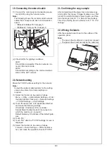
(1) Connect the main body and networking equip-

ment (HUB) using the network cable.

Note:

The following shows the recommended network 
cables that correspond to each communication 
speed.

    • 10BaseT/100BaseTX: Category 5
    • 1000BaseT: Category 5E, Category 6

(2) Check LEDs for lighting conditions.

LED1:
Should light up steadily if the link network con-
nection has been made.
LED2:
Should blink according to the communications 
status of the ACT network.

20. Network setting

Make the TCP/IP address setting for the network.

Note:

Consult the network administrator for the setting 
value to be entered and make settings as 
required.

(1) Select the function to be used as follows:

Menu 

o

 Utility 

o

 Administrator Settings 

o

 Enter 

the Administrator Password 

o

 Network Settings 

o

 TCP/IP Settings 

o

 IPv4 Settings.

(2) Touch “Manual Input” of IP Application Method 

and make the following settings.
IP Address: IP address of the controller
Subnet Mask: Subnet mask of the network, to 
which the machine is connected
Default Gateway: IP address of the default gate-
way

(3) Touch “OK.”
(4) Touch “OK” after the “TCP/IP Settings” screen is 

displayed.

(5) Select the function to be used as follows:

Forward 

o

 Detail Settings 

o

 PING Confirma-

tion, and make the operation check of TCP/IP.

21. Confirming the copy sample

After completing all the steps, take a sample copy 
and confirm the image. If image troubles occur, first 
turn OFF and ON the Main Power Switch, and then 
redo the steps from E-7 “12. Date & Time Setting/
Time Zone Setting (Service Mode)” to E-7 “14. Unit 
change.” 

22. Affixing the labels

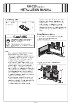
Affix the supplied panel sheet to the surface of the 
operation panel.

Note:

    • The panel sheet is affixed on customer request.
    • The panel sheet must be kept by the customer.

Networkport

LED2

LED1

Содержание bizhub 4052

Страница 1: ...esponding installation manual and perform the procedures correctly Once the Power Switch is turned ON do not turn OFF it until the installation work has been completed Caution Lifting the machine in an awkward position or transporting it in a poorly balanced position could result in personal injury When transporting the machine assign an adequate number of persons to the job and ensure that each p...

Страница 2: ... sunlight 6 Avoid a dusty location or a place near volatile and flammable substances 7 Avoid a poorly ventilated place 4 Notes on using touch panel Be sure to instruct users on the following points This machine uses a capacitive touch panel When you touch the touch panel use your fin ger or the stylus pen for the capacitive touch panel If you touch the panel using your nail or a pen tip instead of...

Страница 3: ...allation manual 1 set 3 User s guide CD 1 4 DVD 1 5 Panel sheet 1 6 Power cord 1 Keep this bag away from babies and children Do not use in cribs beds carriages or playpens The thin film may cling to nose and mouth and prevent breathing This bag is not a toy If a power cord is not supplied use only the power cord that meets the following conditions Failure to do this could result in a fire or elect...

Страница 4: ...e all protective tapes and protective mate rials used for fixing the machine housing 3 Open the automatic document feeder ADF and remove the protective tape and protective mate rial 4 Press the front door button to open the front door 5 Hold the handle and slowly pull out the toner car tridge 6 Hold the handle and slowly pull out the imaging unit ...

Страница 5: ...e the protective materials from the imag ing unit Note Do not touch the photo conductor 9 Reinstall the imaging unit Note Align the arrows on the imaging unit with the arrows on the machine 10 Hold the handle and shake the toner cartridge from front to back and from side to side ...

Страница 6: ...chine 12 Close the front door 13 Slide out the tray 1 and remove the protective materials from the inside of the tray 8 Loading the tray 1 1 Slide the paper guides to the appropriate paper size 2 Fix the paper guide 3 Set paper with the printing side downward 4 Reinstall the tray 1 5 Slide out the exit guide ...

Страница 7: ... is entered correctly To return to the basic screen turn OFF the main power switch and turn it ON again When Administrator Settings Security Settings Security Details Prohibited Functions When Authentication Error is set to Mode 2 operation will be prohibited since it indicates authentication failure by failing to enter the correct CE password within the specified number of times If the access loc...

Страница 8: ...he directions on the screen to input numerical values NOTE For more details see the description pages for each setting item 3 Touch END This closes the setting screen and returns to the Service Mode screen If deep within the hierarchy of the setting screen it may be necessary to touch END several times 4 Touch Exit This will close the Service Mode screen and exit the Service Mode 5 Turn OFF the ma...

Страница 9: ...zhub 4752 4052 H SERVICE MODE 4 Exiting procedure H 4 4 Exiting procedure 1 Touch Exit on the Service Mode screen 2 Turn OFF the main power switch Wait 10 seconds then turn ON the main power switch again ...

Страница 10: ...e control panel 3 Do not input date and time but touch Entry of the Date Time Setting 4 Input the time zone using up down keys or direct keys 5 Touch Entry of the Time Zone Setting 6 Touch Apply 7 Touch OK 8 Touch Next 13 Serial number input Note Serial number input is if necessary needed only for the optional devices installed in 9 Installing options 1 Touch the item you want to enter and input t...

Страница 11: ...on procedures of the installa tion manual for each option and configure the option s Authentication Unit AU 201S AU 102 Upgrade Kit UK 216 Fax Kit FK 517 Local Interface Kit EK P06 Network Fax 2 Exit from the Service Mode and return to the ini tial screen 17 Setting up wireless connection kit only for North America models 1 Display the Service Mode screen For details of how to display the Service ...

Страница 12: ...ettings o TCP IP Settings o IPv4 Settings 2 Touch Manual Input of IP Application Method and make the following settings IP Address IP address of the controller Subnet Mask Subnet mask of the network to which the machine is connected Default Gateway IP address of the default gate way 3 Touch OK 4 Touch OK after the TCP IP Settings screen is displayed 5 Select the function to be used as follows Forw...

Страница 13: ...e application and printer driver When your customer bought i Option LK 104 v3 license kit for audio guide function copy audio guide data from the USB flash drive and install it to the machine For details on the installation method see service manual This manual provides the illustrations of the accessory parts and machine that may be slightly different in shape from yours In that case instead of t...

Страница 14: ...oved in step 3 Two screws 7 Close the right door 3 Configuration procedures Check after the memory has been Installed 1 Plug the power cord into the power outlet and turn ON the power switch 2 Display the Service Mode screen For details of how to display the Service Mode screen see the service manual 3 Touch State Confirmation 4 Touch Memory Storage Status 5 Make sure that the volume of memory was...

Отзывы: