


Seatex Seapath 200 Installation Manual, rev. 13
Appendix D – Seapath configuration software, SCC
98
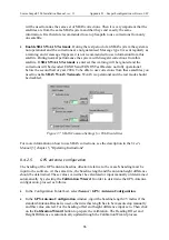
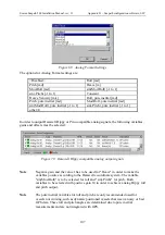
For more details on selection of heave filter mode and parameters, see the
User's Manual
. In
order to select the heave configuration proceed as follows:
•
In the Configuration Folder List, select
Sensor \ MRU \ Heave Config.
•
Enter the settings for Filter Mode and Filter Parameters. The pull-down Filter Mode menu
has the following options; Integrated, Automatic, Hydrographic survey or General
purpose. In Integrated, Hydrographic survey and General purpose mode, the filter
parameter for Period can be set to a value between 1 and 25 seconds, and the Damping
value between 0.2 and 1.
Figure 53 MRU Heave Filter
•
Click on the checkbox "Heave mean level is roll/pitch dependent" to make the heave
measurement dependent on the roll and pitch measurements. Then the heave position in
the measurement points (MP) has now longer zero mean level, instead its value depends
on the vessel tilt at any time. This option is useful especially in applications where the
distance between the MP and the sea level is to be determined, like in echo sounder
installations with depth changes due to changes in vessel trim and list. If this mode is not
selected, the heave will always have zero mean level.
8.4.4
Measurement points
8.4.4.1
Measurement points geometry
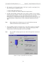
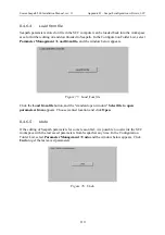
In Seapath up to four different measurement points for output data can be defined. The lever
arm vector from the centre of gravity to each measurement point has to be measured or
calculated based upon drawings or previously measured points, and entered into the software.
These vectors are to be measured with an accuracy of 0.5 metres. Proceed as follows to enter
the measurement point vectors:
•
In the Configuration Folder List, select
Measurement Points \ Geometry.
•
Enter a vector and a name for each of the measurement points needed for the installation.
Tick off the measurement points that should be active. Check that the measurement points
have been located on the expected points in the "vessel window". If not, check the signs
and the co-ordinates input for each measurement point, the vessel dimension and the
entered location of CG.
Содержание Seatex Seapath 200
Страница 1: ...Seatex Seapath 200 Installation Manual Issued 2008 06 09 ...
Страница 2: ...Blank page ...
Страница 4: ...IV Blank page ...
Страница 6: ...VI Blank page ...
Страница 10: ...X Blank page ...
Страница 14: ...XIV Blank page ...
Страница 18: ...Seatex Seapath 200 Installation Manual rev 13 Introduction 4 Blank page ...
Страница 22: ...Seatex Seapath 200 Installation Manual rev 13 Specifications 8 Blank page ...
Страница 53: ...Seatex Seapath 200 Installation Manual rev 13 Installation drawings 39 ...
Страница 54: ...Seatex Seapath 200 Installation Manual rev 13 Installation drawings 40 ...
Страница 55: ...Seatex Seapath 200 Installation Manual rev 13 Installation drawings 41 ...
Страница 56: ...Seatex Seapath 200 Installation Manual rev 13 Installation drawings 42 ...
Страница 64: ...Seatex Seapath 200 Installation Manual rev 13 Appendix A Installation worksheet 50 Blank page ...
Страница 80: ...Seatex Seapath 200 Installation Manual rev 13 Appendix C Installation of coax connectors 66 ...
Страница 81: ...Seatex Seapath 200 Installation Manual rev 13 Appendix C Installation of coax connectors 67 ...
Страница 82: ...Seatex Seapath 200 Installation Manual rev 13 Appendix C Installation of coax connectors 68 ...
Страница 83: ...Seatex Seapath 200 Installation Manual rev 13 Appendix C Installation of coax connectors 69 ...
Страница 84: ...Seatex Seapath 200 Installation Manual rev 13 Appendix C Installation of coax connectors 70 Blank page ...
Страница 126: ...Seatex Seapath 200 Installation Manual rev 13 Appendix D Seapath configuration software SCC 112 Blank page ...


