Seatex Seapath 200 Installation Manual, rev. 13
Appendix D – Seapath configuration software, SCC
92
8.4.3
MRU sensor settings
8.4.3.1
MRU
geometry
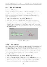
The lever arm vector from the centre of gravity to the MRU location has to be measured or
calculated based upon drawings or previously measured points, and entered into the software.
This vector is to be measured with an accuracy of 0.5 metres. Proceed as follows to enter the
MRU lever arm:
•
In the Configuration Folder List, select
Sensor \ MRU \ Geometry.
•
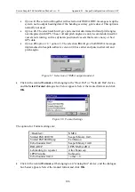
Enter the settings for MRU Lever Arm. Look at the sketch of the MRU geometry on the
screen in order to enter correct signs on the co-ordinates. Check also that the MRU has
been located on the expected spot in the "vessel window". If not, check the signs and the
co-ordinates input for the MRU, the vessel dimension and the entered location of CG.
Figure 46 MRU Geometry
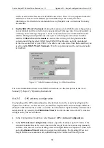
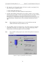
The MRU mounting angles can either be input manually or determined by use of the MRU
Mounting Wizard. To use the MRU Mounting Wizard proceed as follows:
•
Click the
MRU Mounting Wizard
button to get to Step 1 of the MRU axis orientation.
Choose to continue with Manual or Automatic setup of mounting angles.
Содержание Seatex Seapath 200
Страница 1: ...Seatex Seapath 200 Installation Manual Issued 2008 06 09 ...
Страница 2: ...Blank page ...
Страница 4: ...IV Blank page ...
Страница 6: ...VI Blank page ...
Страница 10: ...X Blank page ...
Страница 14: ...XIV Blank page ...
Страница 18: ...Seatex Seapath 200 Installation Manual rev 13 Introduction 4 Blank page ...
Страница 22: ...Seatex Seapath 200 Installation Manual rev 13 Specifications 8 Blank page ...
Страница 53: ...Seatex Seapath 200 Installation Manual rev 13 Installation drawings 39 ...
Страница 54: ...Seatex Seapath 200 Installation Manual rev 13 Installation drawings 40 ...
Страница 55: ...Seatex Seapath 200 Installation Manual rev 13 Installation drawings 41 ...
Страница 56: ...Seatex Seapath 200 Installation Manual rev 13 Installation drawings 42 ...
Страница 64: ...Seatex Seapath 200 Installation Manual rev 13 Appendix A Installation worksheet 50 Blank page ...
Страница 80: ...Seatex Seapath 200 Installation Manual rev 13 Appendix C Installation of coax connectors 66 ...
Страница 81: ...Seatex Seapath 200 Installation Manual rev 13 Appendix C Installation of coax connectors 67 ...
Страница 82: ...Seatex Seapath 200 Installation Manual rev 13 Appendix C Installation of coax connectors 68 ...
Страница 83: ...Seatex Seapath 200 Installation Manual rev 13 Appendix C Installation of coax connectors 69 ...
Страница 84: ...Seatex Seapath 200 Installation Manual rev 13 Appendix C Installation of coax connectors 70 Blank page ...
Страница 126: ...Seatex Seapath 200 Installation Manual rev 13 Appendix D Seapath configuration software SCC 112 Blank page ...


