


Seatex Seapath 200 Installation Manual, rev. 13
Appendix D – Seapath configuration software, SCC
86
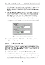
will be used to make the same set of SBAS corrections. Then it is very important that the
satellites are from the same SBAS system and that they send exactly the same
information. It is therefore recommended to set up Seapath to use corrections from only
one satellite.
•
Enable SBAS WAAS Testmode
. During the test period of an SBAS system the system is
not operational and the corrections are not guaranteed. Message type 0 is sent regularly as
a warning and if message 0 appears it is not recommended to use information from this
satellite. During normal performance the system will disregard corrections from this
satellite. If
SBAS WAAS Testmode
is entered, this warning will be ignored and the
corrections will be decoded. EGNOS and EGNOS Test Bed are not fully operational
before the second half of year 2004. To be able to use corrections from these satellites you
need to enable
SBAS WAAS Testmode
. WAAS is operational and the test mode should
be disabled.
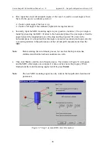
Figure 37 SBAS Common Settings for WAAS satellites
For more information on how to use SBAS corrections, see the description in the
User's
Manual
[3] chapter 5, "Operating Instructions".
8.4.2.5
GPS antenna configuration
The heading of the GPS antenna baseline direction relative to the vessel's heading must be
input to the software. At the same time, the baseline length and the antenna height difference
should be determined. These values can either be calculated or input manually or determined
automatically by selecting the
Calibration Wizard
. In order to determine the GPS Antenna
configuration, proceed as follows:
•
In the Configuration Folder List, select
Sensor \ GPS \ Antenna Configuration
.
•
In the
GPS Antenna Configuration
window, input the baseline length 2.5 metres if the
standard Antenna Bracket is used, otherwise this length has to be measured up manually
and this value entered. For the heading offset and height difference input zero. Then click
on the
Calibration Wizard
button to prepare the calibration. The Heading Offset and
Height Difference is automatically updated trough the Calibration Wizard process.
Содержание Seatex Seapath 200
Страница 1: ...Seatex Seapath 200 Installation Manual Issued 2008 06 09 ...
Страница 2: ...Blank page ...
Страница 4: ...IV Blank page ...
Страница 6: ...VI Blank page ...
Страница 10: ...X Blank page ...
Страница 14: ...XIV Blank page ...
Страница 18: ...Seatex Seapath 200 Installation Manual rev 13 Introduction 4 Blank page ...
Страница 22: ...Seatex Seapath 200 Installation Manual rev 13 Specifications 8 Blank page ...
Страница 53: ...Seatex Seapath 200 Installation Manual rev 13 Installation drawings 39 ...
Страница 54: ...Seatex Seapath 200 Installation Manual rev 13 Installation drawings 40 ...
Страница 55: ...Seatex Seapath 200 Installation Manual rev 13 Installation drawings 41 ...
Страница 56: ...Seatex Seapath 200 Installation Manual rev 13 Installation drawings 42 ...
Страница 64: ...Seatex Seapath 200 Installation Manual rev 13 Appendix A Installation worksheet 50 Blank page ...
Страница 80: ...Seatex Seapath 200 Installation Manual rev 13 Appendix C Installation of coax connectors 66 ...
Страница 81: ...Seatex Seapath 200 Installation Manual rev 13 Appendix C Installation of coax connectors 67 ...
Страница 82: ...Seatex Seapath 200 Installation Manual rev 13 Appendix C Installation of coax connectors 68 ...
Страница 83: ...Seatex Seapath 200 Installation Manual rev 13 Appendix C Installation of coax connectors 69 ...
Страница 84: ...Seatex Seapath 200 Installation Manual rev 13 Appendix C Installation of coax connectors 70 Blank page ...
Страница 126: ...Seatex Seapath 200 Installation Manual rev 13 Appendix D Seapath configuration software SCC 112 Blank page ...


