22
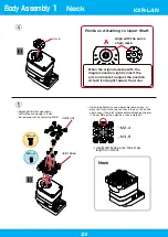
Body Assembly 1
Neck
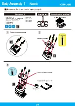
Joint base
Joint nut
*Attach M3-8 after tightening
M2-4. When removing it, it can
be removed just by removing M3-8.
Horn B
⑤
Neck
M2 -4
M3 -8
M2 ー 4
x4
M3 ー 8
④
Align with the servo
origin mark.
Points on Attaching to Upper Shaft
A
When the origin deviates with the
diagram position, lightly insert the
arm and rotate to adjust the position.
Attach it straight toward the A line.
*Use M3-8. Make sure the screw
length is correct.
*It would be helpful to use a paint marker pen, etc. to
mark the front of the joint so that it is easy to find the
origin even if the joint rotates before attaching the arm.
(The nut M2 part can also be cut and marked.)
KXR-L4N
Содержание KXR-L4N
Страница 34: ...34 Head Assembly 1 Gripper M2 6 ー 10 Joint frame 3300A Joint frame 3300A Gripper M2 6 ー 10 KXR L4N ...
Страница 36: ...36 Head Assembly 2 Join M2 6 ー 10 M2 ー 6 x4 Botom arm 3300 38 Cable guide X 2 6 ー 4 Head 200mm KXR L4N ...
Страница 42: ...42 Complete Assembly completed KXR L4N ...
Страница 65: ......


