REMOVAL OF THE BOOM SWING CYLINDER
Lower the working equipment to the ground with all
safety devices engaged. Rest the back of the bucket
on the ground with the arm in a verticalposition.
1 - Stop the engine and move the command pedalseve-
raltimes to release residualpressures.
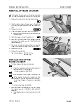
2 - Raise the floor mat (1) and remove the right-hand side
panel(2).
3 - Make a note of the position of the shims of the cylin-
der and the piston rod.
4 - Place a supporting adjustment «A» beneath the cylin-
der.
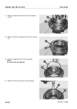
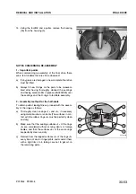
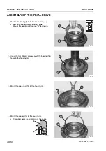
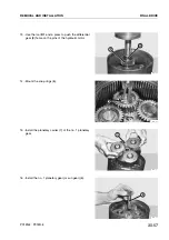
5 - Remove the pin (2) and disengage the piston rod from
its support (3).
6 - Start the engine and retract the piston rod (4).
H
Bind the piston rod with wire to secure the fully re-
tracted position.
7 - Stop the engine and release any residual hydraulic
pressures. (For details, see «20. CONTROLS AND
ADJUSTMENTS»).
8 - Disconnect the hoses (5) and plug them. Also plug
the holes in the cylinder (6) to prevent entry of impu-
rities.
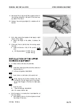
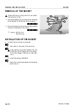
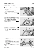
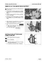
9 - Remove the pin (7) on the base side and remove the
cylinder.
Boom swing cylinder: PC12R: 10 kg
PC15R: 10 kg
INSTALLATION OF THE
BOOM SWING CYLINDER
.
To install, reverse the removal procedure.
H
Insert the shims above the piston rod.
When aligning the positions between the hole
and the pin, turn the engine over at low idling.
Do not insert fingers in the holes to check align-
ment.
Internalbushings: ASL800040
H
Insert the shim.
.
Start the engine and bleed the air from the cylinder.
(For details, see «20. CONTROLS AND ADJUST-
MENTS»).
H
After bleeding the air, check the oil level in the
tank.
30-66
REMOVAL AND INSTALLATION
BOOM SWING CYLINDER
PC12R-8 PC15R-8
RKPA1330
1
2
RKPA1340
4
2
3
A
RKPA1350
7
6
5
RKPA1350
7
6
5
Содержание PC12R-8 MISTRAL
Страница 1: ......
Страница 2: ...40 28 PC15R 8 ...
Страница 4: ...00 2 PC12R 8 PC15R 8 ...
Страница 17: ...GROUP 10 ...
Страница 18: ...40 28 PC15R 8 ...
Страница 30: ...10 12 PC12R 8 PC15R 8 PAGE INTENTIONALLY LEFT BLANK ...
Страница 32: ...10 14 PC12R 8 PC15R 8 PAGE INTENTIONALLY LEFT BLANK ...
Страница 34: ...10 16 PC12R 8 PC15R 8 PAGE INTENTIONALLY LEFT BLANK ...
Страница 36: ...10 18 PC12R 8 PC15R 8 PAGE INTENTIONALLY LEFT BLANK ...
Страница 38: ...10 20 PC12R 8 PC15R 8 PAGE INTENTIONALLY LEFT BLANK ...
Страница 40: ...10 22 PC12R 8 PC15R 8 PAGE INTENTIONALLY LEFT BLANK ...
Страница 42: ...10 24 PC12R 8 PC15R 8 PAGE INTENTIONALLY LEFT BLANK ...
Страница 44: ...10 26 PC12R 8 PC15R 8 PAGE INTENTIONALLY LEFT BLANK ...
Страница 79: ...10 61 PC12R 8 PC15R 8 PAGE INTENTIONALLY LEFT BLANK ...
Страница 130: ...10 112 PC12R 8 PC15R 8 PAGE INTENTIONALLY LEFT BLANK ...
Страница 132: ......
Страница 133: ...GROUP 20 ...
Страница 134: ...40 28 PC15R 8 ...
Страница 149: ...PC15R 8 Standard value Permissible value Max 20 Max 30 2 Max 5 2 Max 5 2 Max 5 FOR THE MACHINE 20 15 PC12R 8 PC15R 8 ...
Страница 158: ...20 24 PC12R 8 PC15R 8 PAGE INTENTIONALLY LEFT BLANK ...
Страница 198: ......
Страница 199: ...GROUP 30 ...
Страница 200: ...40 28 PC15R 8 ...
Страница 283: ...GROUP 40 ...
Страница 284: ...40 28 PC15R 8 ...
Страница 295: ...HYDRAULIC PUMP PC12R 8 40 11 PC12R 8 PC15R 8 RKP00910 Z Vista Z 68 6 Nm 7 kgm 48 Nm 4 9 kgm View Z ...
Страница 298: ...40 14 PC12R 8 PC15R 8 RKP00131 Sezione A A 44 1w4 9 Nm 4 5w0 5 kgm 44 1w4 9 Nm 4 5w0 5 kgm Section A A ...
Страница 304: ...40 20 PC12R 8 PC15R 8 RKP00201 Sezione A A 44 1w4 9 Nm 4 5w0 5 kgm 44 1w4 9 Nm 4 5w0 5 kgm Section A A ...
Страница 317: ...40 33 PC12R 8 PC15R 8 PAGE INTENTIONALLY LEFT BLANK ...
Страница 324: ......

