AKD-N Installation | 7 Technical description and data
7.14.10 Functional description local STO
With AKD-N with option DS or DT, an additional digital input (STO) releases the power output
stage of the drive as long as a 24 V signal is applied to this input. When the local STO func-
tion (Safe Torque Off) is not needed, then the input STO must be connected directly to +24
VDC. The function is then bypassed and cannot be used.
The global STO signal will have no influence to this drive. The local STO input on the AKD-N
has no influence to the global STO as well.
Local
STO-Enable
String
HW Enable
Local
STO-Status
Safety acc.
to SIL2
Drive can
produce Torque
0 V
no
high
yes
no
0 V
yes
high
yes
no
+24 V
no
low
no
no
+24 V
yes
low
no
yes
When STO function is engaged during operation by separating input STO-Enable from 24 V,
the connected motor slows down without control.
Use the following functional sequence when the STO function is used:
1. Brake the drive in a controlled manner (speed setpoint = 0 V).
2. When speed = 0 rpm, disable the drive (enable = 0 V).
3. If a suspended load is present, block the drive mechanically.
4. Activate the STO function.
It is not possible to perform a controlled brake if the drive STO-Enable is off.
If controlled braking prior to the use of the STO function is necessary, the drive must be
braked first and the input STO must be separated from +24 V time-delayed.
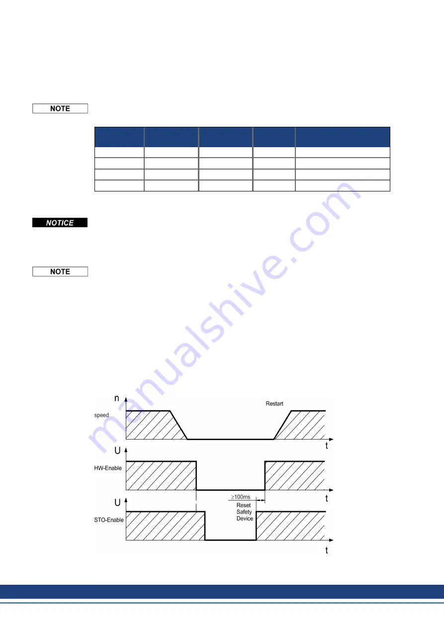
7.14.10.1 Signal diagram (sequence)
The diagram below shows how to use STO function for a safe drive stop and fault free oper-
ation of the drive. This sequence is valid for local and global STO functionality.
1. Brake the drive in a controlled manner (speed setpoint = 0 V).
2. When speed = 0 rpm, disable the drive (Enable = 0 V).
3. Activate the STO function (local STO-Enable = 0 V)
4. For restart you must reset the safety device.
46
Kollmorgen | kdn.kollmorgen.com | February 2018


