background image

44

9. Detailed Configuration of the Virtual Vaginal Exam

If required, the Operation Environment can be configured and the model display position adjusted.

1) Operation Environment Setup

To configure the operation Environment for the application, select "Setup" and then "Operation 
Environment" from the menu, and use the "Operation Environment Setup" dialog box that is 
displayed.
The updated Setup are reflected when the [Apply] button is clicked. To close the dialog box at the 
same time that the updated Setup are applied, click the [OK] button.
If the dialog box is closed using the [Cancel] button or the [X] button before the updated Setup are 
applied, the Setup will be returned to their previous values.

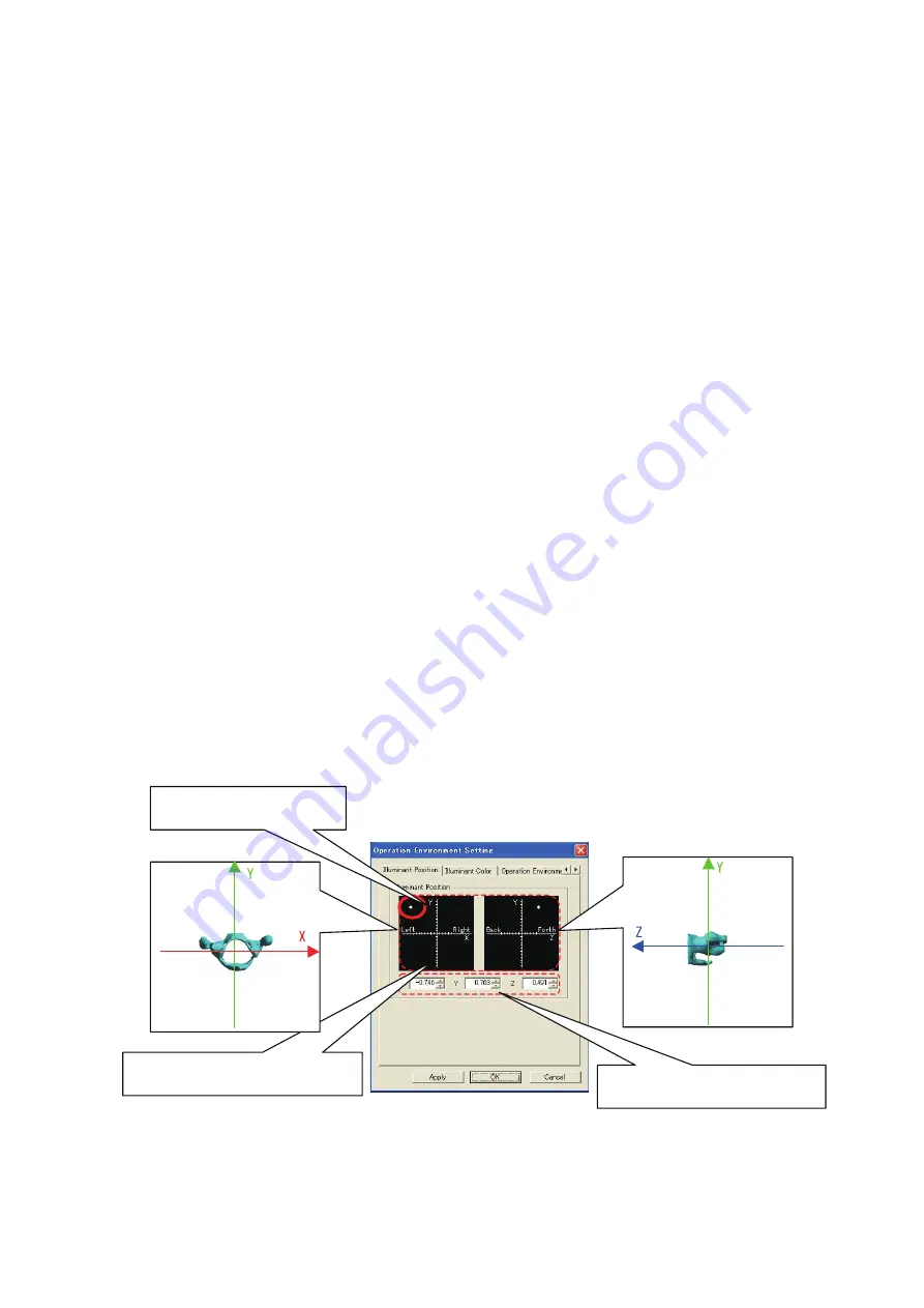
(1) Light source position
This is used to set the position of the light source. 
In the notations on the Setup window, “Left” and “Right” correspond to the X axis direction, while 
“Up” and “Down” correspond to the Y axis direction, and “Forward” and “Backward” correspond 
to the Z axis direction. The initial viewpoint is on the + side of the Z axis (the “front” of the setting 
screen).
Enter the position by either clicking on "Light Source Position Setting Diagram”, or by entering the 
values in “Light Source Position Setting Values”. A value may be entered within a range of -1 to 1.

Current light source position


Light Source Position Setting Diagram


Up 


Left

Up 


Light Source Position Setting Values

Down


Down

Right 

Front

Back  

Содержание LM-095N

Страница 1: ...ity Vaginal Exam Model II Please read this instruction manual carefully to ensure correct use of the product and store it in a safe place for easy access KOKEN CO LTD 1 4 14 Koraku Bunkyo ku Tokyo 112...

Страница 2: ......

Страница 3: ...is not responsible for deterioration or damage to the model occurring from use of lubricants other than glycerin When the glycerin provided runs out use commercially available glycerin 4 Placing objec...

Страница 4: ...rs 18 The Virtual Reality Vaginal Exam Model may react to magnetic fields causing the model to malfunction When using the Virtual Reality Vaginal Exam Model keep computers and objects that generate ma...

Страница 5: ...ews installed to keep water from getting inside the main body If the exclusive screws are not installed water may get inside the main body through the screw holes 5 To clean the finger sensors disconn...

Страница 6: ...ing Applications 4 Exit 5 Fetal Head Rotation 3D Graphics Operation 1 Launching the Fetal Head Rotation 3D Graphics Application 2 Animation Operation 3 Viewpoint Operation 6 Setting Up the Virtual Vag...

Страница 7: ...osely approximates that of real tissue The cervix and other structures can be checked under highly realistic conditions 4 The images are three dimensional and can be freely moved on the computer enabl...

Страница 8: ...xclusive screws Base for securing main body Finger sensors trakSTAR for index finger and second finger USB cable Power cable 1 2 cm uterus dilation model 3 4 cm uterus dilation model 8 9 cm uterus dil...

Страница 9: ...D Plastic wagon Cloth cover Finger sensors are available in three finger sizes S M and L The S M and L finger sack sizes are equivalent to surgical glove sizes 6 7 and 8 trakSTAR is a trademark of Asc...

Страница 10: ...tc or higher recommended USB ports 2 ports these are used to connect the trakSTAR and product key when operating the model Three USB ports are required if the computer does not have an internal CD dri...

Страница 11: ...e plastic wagon and insert the cable coming from the main body base into the terminal labeled Transmitter on the trakSTAR 4 Connect the finger sensors to Sensors 1 and 2 on the trakSTAR Be careful not...

Страница 12: ...connector Attaching or removing the connector by pulling on the cable could cause the cable to break Follow the outlines below when connecting and disconnecting the finger sensors Connecting Hold the...

Страница 13: ...USB cable is inserted into any location other than the USB port on the computer to which the cable was connected at the time of installation Decide in advance which USB port is to be used for connect...

Страница 14: ...e following screen appears Click Accept Depending on your computer Setup the figure below may be skipped and Screen 5 may appear in which case proceed with installation from Step 5 below If NET Framew...

Страница 15: ...13 5 The following screen appears Click Next 6 Select Just me and click Next Click here Click here Click here Select Just me...

Страница 16: ...The following screen appears Click Next 8 The Installation screen appears and installation commences 9 When message appears on the screen whether you wish to install or not please click Install Click...

Страница 17: ...ollowing screen appears Click Next 11 The following screen appears Click Close 12 Turn on the power to the trakSTAR 13 Please insert the product key to USB port on the computer Click here Click here P...

Страница 18: ...e to select the language to be displayed when operating the Virtual Reality Vaginal Exam Model 15 When the language is selected the following screen appears Double click on Setup msi to run 16 When Se...

Страница 19: ...ses the computer to use the Virtual Reality Vaginal Exam launch shortcut created during installation 18 Click Next to move to the Confirm Installation screen Click on Next 19 The Installation screen a...

Страница 20: ...tallation the Installation Complete screen appears Click the Close button to close the screen and complete installation 22 When installation ends shortcuts are created on the Start Menu and on the Des...

Страница 21: ...pleting the installation a dialogue box indicating that the operation has been completed successfully is displayed as shown in the figure below If you do not insert a space before i the installation i...

Страница 22: ...talled driver and try again See p 21 Deleting the driver 25 After completing the installation right click the shortcut icon created on the desktop and then select properties 26 Check the Run this prog...

Страница 23: ...d press the Enter key to delete the driver After the deletion is complete a dialogue box indicating that the operation has been completed successfully is displayed as shown in the figure below 3 Doubl...

Страница 24: ...22 4 When the screen shown in the figure below appears click Y 5 After the driver has been deleted install the driver again 21 4 Y 5...

Страница 25: ...evE 2 Double click on Install msi 3 The same screen as shown in Section 3 7 Installing the application on p 14 will appear Click Next to run installation from step 5 p 13 5 Uninstalling the applicatio...

Страница 26: ...the Start menu or the desktop shortcut The product key must be connected to a USB port for the application to launch If it is not connected the following dialog box will appear and the application wil...

Страница 27: ...intsofview insequentialorder 1 Viewfromthefeetofthemainbody 2 Viewfromtherightsideofthemainbody 3 Viewfromtheleftsideofthemainbody 4 Viewfromtheabdomenofthemainbody 5 Viewfromthebackofthemainbody Back...

Страница 28: ...d of the track bar representing the start of the animation and the right end representing the end of the animation The current playback time can be changed by dragging the with the left mouse button P...

Страница 29: ...lel movement Drag direction The image moves parallel to the drag direction Drag direction upward Dragging upward zooms in Dragging downward zooms out Drag direction downward Drag direction The image m...

Страница 30: ...sensors to the fingers ensuring that the sensor parts are over the fingernails After the finger sacks are in place apply baby powder to the sacks 4 After the finger sacks are in place put on the glov...

Страница 31: ...are displayed in green on the computer screen as shown below The fingers on the screen move in accordance with the actual movement of the finger sensors See Section 1 on p 29 Launching the Virtual Va...

Страница 32: ...us dilation model on the plate that secures it in place and tighten the exclusive screws to secure the uterus dilation model in place 1 Setting the 1 2 cm and 3 4 cm uterus dilation models in place Va...

Страница 33: ...lation model secured to it After setting it in place close the doors to secure the plate in place The Virtual Reality Vaginal Exam Model may react to magnetic fields causing the model to malfunction W...

Страница 34: ...to place the base that secures the main body on the upper level of the plastic wagon provided as an accessory and place the trakSTAR on the lower level Before practicing check to make sure that the st...

Страница 35: ...linking green again After that the light changes to a steady green display indicating that the application can now be used When the examination training session is over exit the Virtual Vaginal Exam a...

Страница 36: ...istance measurements For detailed information see Section 8 3 3 Measurement on p 37 Operation Environment This turns the Operation Environment d ialog box display on and o The Operation Environment di...

Страница 37: ...ys the Select Images dialog box This can be used to make simple adjustments to the display status of the model The following parameters can be adjusted Display on off for each model Uterus model selec...

Страница 38: ...the fetus A RA RT RP P LP LT and LA This feature is only available if the 8 9 cm uterus dilation model or the fetal head model has been selected Light source position selection The light source positi...

Страница 39: ...This dialog box can be used to adjust the display status of the model The following items can be adjusted Transparency Setting on off Transparency level Color Display Type Transparency Setting on off...

Страница 40: ...the transparency of the uterus Changing the color in which the pelvis is displayed The uterus is shown in a wireframe display section Left Cross section Right Cross section Front Cross section Back Ch...

Страница 41: ...mouse button while holding down the SHIFT key Parallel movement Drag direction Direction of dragging The image moves parallel to the drag direction Rotates around an axis perpendicular to the drag dir...

Страница 42: ...and is occupied making it difficult to use the mouse The viewpoint cannot be moved parallel using the keys so the image should be adjusted in advance so that the portion of primary interest is in the...

Страница 43: ...he point at which measurement is carried out are used as the measurement points When Between two fingers is selected as the measurement mode the text on the Measurement button in the Measurement dialo...

Страница 44: ...the measurement points The distance between the two points is displayed in centimeter units to one decimal place b Single finger movement distance This measurements the distance moved by either of th...

Страница 45: ...r finger to the ending point registers the ending point and displays the distance between the starting and ending points Each time a measurement is made the result is displayed on the screen as a cumu...

Страница 46: ...tton before the updated Setup are applied the Setup will be returned to their previous values 1 Light source position This is used to set the position of the light source In the notations on the Setup...

Страница 47: ...same time The following presents an overview of the light source color ambient color and background color Light source color This is the color of the light source itself Parts which become brighter w...

Страница 48: ...ing the sensors Operation Mode is used to set the number of sensors to be used Offset 1 is used to adjust position of the finger or fingers displayed on the screen When the X Y and Z parameters of Off...

Страница 49: ...ce position 0 0 0 using dotted lines The axis for adjustment is the axis displayed in the center of the model using a solid line This is the axis that is going to be adjusted Measurement is used to se...

Страница 50: ...nd then Whole Adjustment Of Model from the menu Model Position is the general term used for the distance moved from the reference position the angle rotated and the enlargement or reduction scale Refe...

Страница 51: ...Scale setting This enlarges or reduces the size of the overall model Setup can be specified individually for the X Y and Z axis directions or the scale can be set for the model as a whole X axisrotati...

Страница 52: ...nt Of Model from the menu Model for adjustment The model for which the position is to be adjusted is selected using the Model for Adjustment pull down menu If the fetus 8 9 cm uterus dilation model an...

Страница 53: ...ion are in the center of the model The angle can be specified individually around the X Y and Z axis and the result will be rotated in the sequence of X axis Y axis Z axis Scale setting This enlarges...

Страница 54: ...If the X button is clicked to close the dialog box without first clicking the Apply button values will return to those values used prior to adjustment This has the same effect as clicking the Cancel...

Страница 55: ...ginal exam II 1 Exclusive screws 2 Base for securingmain body 1 Finger sensor for index nger 1 Finger sensor for second nger 1 trakSTAR 1 USB cable 1 Power cable 1 1 2 cm uterus dilation model 1 3 4 c...

Страница 56: ...54 11 Specifications...

Отзывы: