background image

-11-

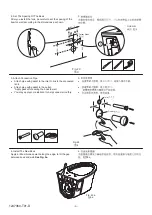
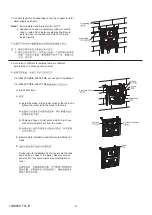
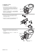
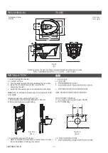
4. 48mm-58mm of the long screw shall be reserved outside

the wall as shown in the illustration. If the long screw
outside the wall is not long enough or much longer than
that needed, it should be adjusted with screwdriver or by
hand. Then apply lubricant to drainage pipe and limber
pipe to ensure a smooth installation.

4.

48mm-58mm

Long Screw

Lubricant

48mm-58mm

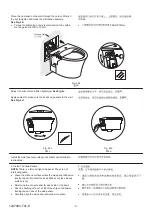
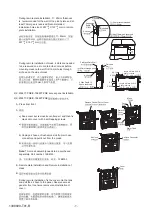
5. Install the Toilet as shown in the illustration, and use a

spirit level to ensure the lavatory to remain level.

5.

Spirit Level

Gasket

Long Screw

Reversed Lock

Hexagonal Nut

Decoration Cap

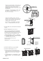
6. Install the reserved lock, gasket, hexagonal nut and

decoration cap onto long screw according to the order
shown in the illustration.

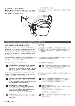
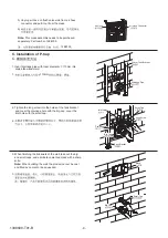
Please refer to the installation instructions of toilet.

Note:

6.

1338609-T01-B

Содержание VEIL K-20534T-S

Страница 1: ...K 5723T Includes HYDRO TOWER 200 PNE In Wall Tank K 20007T VLS Includes Quiet Close Toilet Seat K 4141T VEIL WH Toliet HT300 PNE IWT K 29918T S Includes Bowl K 5723T Includes HYDRO TOWER 300 PNE In Wall Tank K 20010T VLS Includes Quiet Close Toilet Seat K 4141T VEIL WH Toliet HT300 MEC IWT K 29919T S Includes Bowl K 5723T Includes HYDRO TOWER 300 In Wall Tank W Frame K 4179T VLS Includes Quiet Clo...

Страница 2: ... K 21378T CPS K 21378T BNS K 21379T CPS K 21379T BNS 1 K 25094T GS 2 2 VEIL WH Toliet HT100 PNE IWT K 25093T S Includes Bowl K 5723T Includes HYDRO TOWER 100 PNE In Wall Tank with Frame K 22524T VLS Includes Quiet Close Toilet Seat K 4141T VEIL WH Toilet BEAM M FV K 25094T GS Includes Bowl K 24920T GS Includes BEAM Manual Toilet Squat Flush Valve K 77681K G Includes Quiet Close Toilet Seat K 4141T...

Страница 3: ...f faceplate Note Recommended rank dimension Fig 2 b 1 Rank height should be adjust between 0 200mm 2 Rank should support weight 400kg 1 2 Install Manual Valve Or Sensor Refer to installation instructions of manual valve or sensor for the installation of flushing mechanism 1 1 1 2 b 1 0 200mm 2 400kg 1 2 Fig 2 b 2 b 320 135 35 180 400kg 400 10 ROUGHING IN Unit mm Fig 1 1 Reference Value Kohler rese...

Страница 4: ...icant to help connect smoothly 3 Fig 4 4 Inlet Outlet 4 Install The New Bowl Apply a little silicone sealant along the edge to fill the gap between bowl and wall See Fig 5a 4 5a Fig 5a 5a 2 Set The Spacing Of The Bowl After you install the tank be careful to set the spacing of the bowl on wall according to the dimensions as shown 2 Fig 3 3 180 2 135 2 320 1 Carrier Studs Unit mm 25 2 1247360 T01 D...

Страница 5: ...wall See Fig 5d 5c 5d Install the toilet seat according to the toilet seat installation instructions Finished Wall 5 Install The Side Panels There is a left and right side panel They are not interchangeable Clean the vitreous surface where the side panel adhesive locking tape will contact the bowl Make sure the vitreous surface is dry Determine the correct panel for each side of the bowl Peel the ...

Страница 6: ...ny damage to these tank fittings caused by the use of cleaners containing chlorine calcium hypochlorite WARNING Risk of property or product damage Please do not use hard materials like scouring pad to clean product surface especially the product logo CAUTION CAUTION Don t use any cement while installing the toilet WARNING Risk of product damage Heat expansion of the toilet may damage the feet of t...

Страница 7: ...spares not provided by Kohler Water temperature 1 C 45 C Environmental Temperature 1 C 55 C Min water supply 0 02MPa dynamic pressure Max water supply 0 74MPa static pressure This product complies with GB26730 2011 o o o o 1 C 45 C 1 C 55 C 0 02MPa 0 74MPa GB26730 2011 o o o o 3 0 6 0L 100 K 6284T PNE 3 0 4 5L 100 K 22524T PNE 100 3 5 5 0L K 22524T VLS 100 3 5 5 0L K 22524T DNSW 100 3 5 5 0L K 225...

Страница 8: ...ges Of In wall Tank Sustainable to pressure of 400 kg Will not affect the structure of the wall and provides excellent sound insulation Easy installation and time efficient Clean garbage free and space Madeofmacromolecularmaterialsthatpreventscorrison andleaking Adjustabledualflushdesignwhichconserveswater Donotneedtoprepareanyotherspareparts Easymaintenanceandservicing saving RECOMMENDES TOOLS AN...

Страница 9: ...gested 1150 4 Finished Floor 1098 4 1066 4 1048 4 267 5 100 3 35 2 52 230 478 3 438 3 230 3 180 3 667 4 205 3 45 95 143 242 90 0 5 13 62 Method one Press from front Installed with K 22525T PNE K 22525T PNE Method two Remote plate installation Method three Remote installation of mask Air hose Air hose Pinch plate Suggested faceplate installation area R1000mm Suggested faceplate installation area R1...

Страница 10: ...et and supporting feet shall be adjusted per customer ideal height Use leveler to ensure the balance of steel bracket 1 A B Note 2 Drill four holes with diameter of 10mm and depth of 80mm with churn drilling as shown A Fill the bulge nail into the instruction hole on the wall fix the fixing frame to the bulge nail adjust the gasket and tighten the nut B Fill the bulge nail into the instruction hol...

Страница 11: ...ew driver Snap discharge pipe lower end into discharge port 1 A B C B C A Discharge Elbow Discharge Elbow Discharge Elbow Water Tank Bracket Water Tank Bracket Water Tank Bracket Drain outlet 90mm welding 90mm Drain outlet 110mm 110mm Drain outlet 110mm welding 110mm 2 Tighten the long screw into the holes of the tank bracket and cover the drainage hole with the big cap cover the inlet hole with t...

Страница 12: ...s below 4 1 K 22525T PNE K 6283T PNE access panel installation 1 K 22525T PNE K 6283T PNE A A Press from front b Unplug air hose on flush valve side from air hose connector and pull it out from the mask b a Install the mask in the block screen of the tank and tighten the screw to fix the mask to the tank a Mask Screw Water Tank Protective Cover Air Hose Air Hose Connector B Remote plate installati...

Страница 13: ...front A a a b Unplug air hose on flush valve side from air hose connector and pull it out from the mask b This mask assembly needs to be purchased separately Part number 1288193 1288193 Keep cover but remove its central part and then fix mask onto cover with 4 self tapping screws Note Mask Screw Water Tank Cover Protective Cover Remove Central Part of Cover B Remote plate installation and Remote i...

Страница 14: ...3 K 23055T PNE There is only remote installation with K 23055T PNE During remote installation fix the cover onto the tank and pull the air hose to the panel Reserve access panel at front to ensure removal and installation of cover Cover Recommended installation hole size of 146 X 41 mm 146 X 41 mm 41 146 2 0 2 0 Pinch Plate Wall Thickness 7 40mm 7 40mm Adjust length of pinch plate in accordance wi...

Страница 15: ...t Hole Drainage Hole Big Cap Tank Bracket Small Cap 3 When finishing the brickwork of the wall take out the big and small caps and eliminate unwanted mask with a sharp knife When building the wall the product cannot be cast and filled by cement or be squeezed Note 3 Mask Big Cap Small Cap b Unplug air hose on flush valve side from air hose connector and pull it out from the mask b Note This mask a...

Страница 16: ...wall 1 Inlet Pipe Outlet ipe P D Installation of Toilet D 2 Eliminate unwanted part of the pipe and outlet pipe according to the marks of reserved space and rasp a smooth surface with files inlet 2 Inlet Pipe Reserved Space Outlet ipe P 3 Install the big and small leak proof gaskets on inlet pipe and outlet pipe then install it to corresponding pipes on the toilet tank 3 Small Leak proof Gasket In...

Страница 17: ...ber pipe to ensure a smooth installation 4 48mm 58mm Long Screw Lubricant 48mm 58mm 5 Install the Toilet as shown in the illustration and use a spirit level to ensure the lavatory to remain level 5 Spirit Level Gasket Long Screw Reversed Lock Hexagonal Nut Decoration Cap 6 Install the reserved lock gasket hexagonal nut and decoration cap onto long screw according to the order shown in the illustra...

Страница 18: ...Lock Connect to air hose 2 Install the big flush air hose and small flush air hose to the cover Cut the excessive parts of the air hose if necessary Put the lock on the cover directly on the reversed lock on supporting board then push the cover and lock it The installation shall begin from bottom to top Note 2 3 It is ready to use when connected to water supply after installation Reserve access pa...

Страница 19: ... flush air hose and small flush air hose to the cover Cut the excessive parts of the air hose if necessary Put the lock on the cover directly on the reversed lock on supporting board then push the cover and lock it The installation shall begin from bottom to top Note 3 Supporting Board Locknut Fixing Lock Supporting Board Locknut 4 It is ready to use when connected to water supply after installati...

Страница 20: ...tion direction 2 2 Connect air hose to faceplate from water tank 3 3 Insert faceplate into faceplate fixed frame with half flush upward Installation is completed 4 It is ready to use when connected to water supply after installation Reserve access panel at front of the tank in remote installation 4 5 5 How to remove Push Up Pull Out Pull Out 14 1338609 T01 B ...

Страница 21: ...erminal or it may cause damage to the product Insulation measures must be taken at the connection Otherwise short circuit current may occur and damage the transformer Warning 1 2 16 20 AC220V 110V Ceiling Low voltage AC Transformer Output Connector In Tank Output AC 6V AC6V Input AC 220V 110V Black AC220V 110V Transformer Assy Brushing Pipe 2 Faceplate Installation A When tighten four locknuts on ...

Страница 22: ...irectly on the reversed lock on support board then push the cover and lock it The installation shall begin from bottom to top NOTE Cut the excessive parts of air hose if necessary and fix it onto the tank fastener C D Emergency Flush Air Hose Rib A A Slot B B Slot A A Rib B B Ribs on air pump should be assembled into slots on faceplate A A B B Input Signal Cable Input Signal Cable Faceplate Suppor...

Страница 23: ...AND MAINTENANCE OF THE OUTLET VALVE Faceplate Faceplate Connect to air hose Open Close Corner Valve Loosen Nut 2 Turn on or turn off water supply Turn on or turn off water supply by turning the corner valve as shown 2 3 Dismantle supporting board as shown 3 4 Unsnap inlet valve from the bracket 4 Inlet Valve Supporting Board 1338609 T01 B ...

Страница 24: ...ner by hand as shown pull the top of fastener along the direction of arrow Then remove fastener 6 8 Remove discharge valve as shown and then take valve out for cleaning 8 Outlet Valve 7 Pull discharge valve along the arrow direction as shown to remove discharge valve 7 Outlet Valve 1338609 T01 B ...

Страница 25: ...nlet valve Floating box of inlet valve is blocked by tank wall Adjust floating box to appropriate position Floating box of inlet valve is block by waste The adjusting rod of the inlet valve or the floating box is wrapped by the air hose Wash the floating box with clean water Arrange the hose correctly The air hose is loose bent or connected to its apposite button Rearrange the air hose Water level...

Страница 26: ... 20 1338609 T01 B ...
Отзывы: