


:
72
TS_622_02 PowerWAVE 9500DPA User Manual 26/2/19
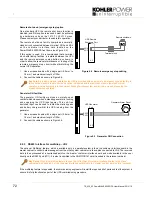
Remote shut down (emergency stop) option
On a standard UPS the remote shut down function is
disabled; and if this option is required it must be activated
by a hardware code on the
SETUP SERVICE
menu.
Please contact your distributor to enable this operation.
The remote shut down facility comprises a normally-
closed circuit connected between terminal X3/3 and X3/4
on the customer interface card located on the
PowerWAVE 9500DPA front frame
(see Figure 9.4)
.
If this option is used, it is recommended that a terminal
block, with linking facilities, is installed between the UPS
and the remote emergency stop button, as shown, in
order to allow the removal, maintenance or testing of the
remote emergency stop circuit without disturbing the
normal UPS operation.
1. Use a screened cable with a single pair (0.5 mm
²
to
1.5 mm
²
) and maximum length of 100m.
2. Connect the cable as shown in Figure 9.4.
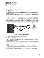
Generator ON facilities
The generator ON facility must use a normally-open
contact which closes when a standby generator is running
and supplying the UPS input power. This volt-free
switched input can be used to inhibit the static bypass
and battery charger whilst the UPS is being from the
generator.
1. Use a screened cable with a single pair (0.5 mm
²
to
1.5 mm
²
) and maximum length of 100m.
2. Connect the cable as shown in Figure 9.5.
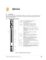
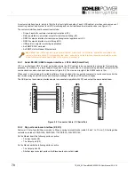
9.2.3 RS485 Interface for multidrop – JR2
The optional ‘Multidrop’ feature, which is available only in a parallel system, allows the customer interface board in the
master cabinet to collect data/messages from the other system cabinets via the cables connected to JD2. The received
data is then processed at a centralised point on the ‘master’ customer interface board and made available to the user
directly on the RS232 port (JD1). It is also transmitted to the SNMP/CS141 card if inserted in the relevant card-slot.
If the multidrop feature is requested, the commissioning engineer will install the required kit of parts and test the system to
ensure it is fully functional as part of the UPS commissioning procedure.
Key Point:
In a single module installation the UPS is provided with an automatic ‘emergency bypass’ facility. In
this case the standard remote shut down option is disabled and the remote shut down (emergency stop)
operation must be designed into the external building/facilities system and include a means of opening the
bypass path when operated.
Key Point:
When the multidrop feature is used the I/O facilities of customer interface boards in the ‘slave’
cabinets are all disabled, but the customer interface board fitted to the ‘master’ cabinet remains fully functional.
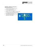
Figure 9.4 Remote emergency stop cabling
X3
X3/4
X3/3
Remote shutdown
Terminal block
UPS Remote
Shutdown Port
Figure 9.5 Generator ON Connection
X3
X3/12
X3/11
Generator Alarm Panel
UPS Generator
Port


