


TS_622_02 PowerWAVE 9500DPA User Manual 26/2/19
5
:
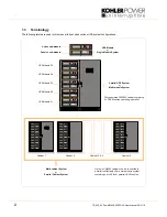
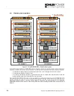
2.3
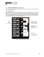
UPS Module functional description
2.3.1 UPS Module internal operation
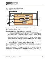
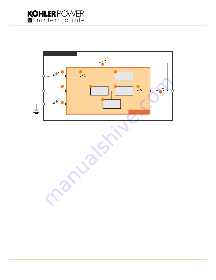
Figure 2.2 UPS module functional block diagram
Figure 2.2 shows an internal functional block diagram of a UPS module installed in a PowerWAVE 9500DPA cabinet.
UPS Module power inputs/outputs (1, 2, 3, 4)
When a UPS module is inserted into the cabinet rack it plugs into a heavy duty power socket located at the rear of the
cabinet which carries the UPS module’s input and output power connections, as shown.
• The UPS input mains (2) is not switched within the cabinet and is connected directly to the UPS module.
• The UPS bypass mains (1) is connected via by fuse F2. Each UPS module is individually fused, with the fuses
labelled F2-x, where ‘x’ denotes the module position within the cabinet. For example the bypass input fuse for the
module fitted to the lowest rack is F2-1, with F2-5 being used to identify the fuse for the top-most module.
• The UPS batteries are installed in an external enclosure and can be configured as a single battery string that is
shared by all the UPS modules (‘common battery’ configuration), or connected as individual battery strings for each
individual module (‘separate battery’ configuration). Irrespective of the external battery configuration, the battery
connection to each UPS module (3) is individually fused by the fuses annotated F3-x, where ‘x’ denotes the module
position within the cabinet, as described above.
• The UPS module a.c. output (4) is connected the cabinet output power terminal via an ‘output isolator’ switch (IA2).
Once again, an individual isolator is provided for each UPS module, annotated IA1-1.... IA1-5. In a redundant-
module parallel UPS system IA2 can be used to disconnect the UPS module from the parallel system output to
allow the module to be replaced, or tested, without affecting the remainder of the system.
Note: In the majority of installations the UPS bypass mains and UPS input mains supplies are linked at the cabinets input
power terminals in what is known as a ‘common input’ configuration. This then requires only one UPS mains supply feed.
Maintenance bypass switch (Optional) (5)
When fitted, the maintenance bypass switch (IA1) (5) provides a means of bypassing ALL the UPS modules fitted in the
PW9500DPA cabinet and connects the cabinet’s output power terminals directly to the UPS bypass mains supply. This
switch can be used to provide the load with unprotected power temporarily if it is necessary to fully power down the UPS
modules. Note that if a maintenance bypass option is required for a multi-cabinet UPS system, the maintenance bypass
switchgear is installed in a separate, external panel and the UPS cabinet internal maintenance bypass switches (IA1) are
not fitted – a typical external maintenance bypass installation is shown on Page 39.
BATTERY
UPS
Input
Mains
UPS
Bypass
Mains
F2
IA1
IA2
F3
UPS AC
Output
Maintenance bypass line
UPS MODULE
PW9500DPA CABINET
RECTIFIER
INVERTER
STATIC
SWITCH
BOOSTER /
CHARGER
Bypass
Contactor
Inv. Output
Contactor
Static bypass line
1
2
3
4
5
6
7
8
9
10
11


