TP-6833 2/16
39
Section 4 Communication and Accessory Connections
4.2.3
Ethernet Connection
Hazardous voltage.
Will cause severe injury or death.
Disconnect all power sources before
opening the enclosure.
DANGER
Servicing the transfer switch. Hazardous voltage can
cause severe injury or death.
Deenergize all power sources
before servicing. Turn off the main circuit breakers of all
transfer switch power sources and disable all generator sets
as follows: (1) Press the generator set off/reset button to shut
down the generator set. (2) Disconnect power to all battery
chargers. (3) Disconnect all battery cables, negative (--) leads
first. Reconnect negative (--) leads last when reconnecting the
battery cables after servicing. Follow these precautions to
prevent the starting of generator sets by an automatic transfer
switch, remote start/stop switch, or engine start command
from a remote computer. Before servicing any components
inside the enclosure: (1) Remove all jewelry. (2) Stand on a
dry, approved electrically insulated mat. (3) Test circuits with a
voltmeter to verify that they are deenergized.
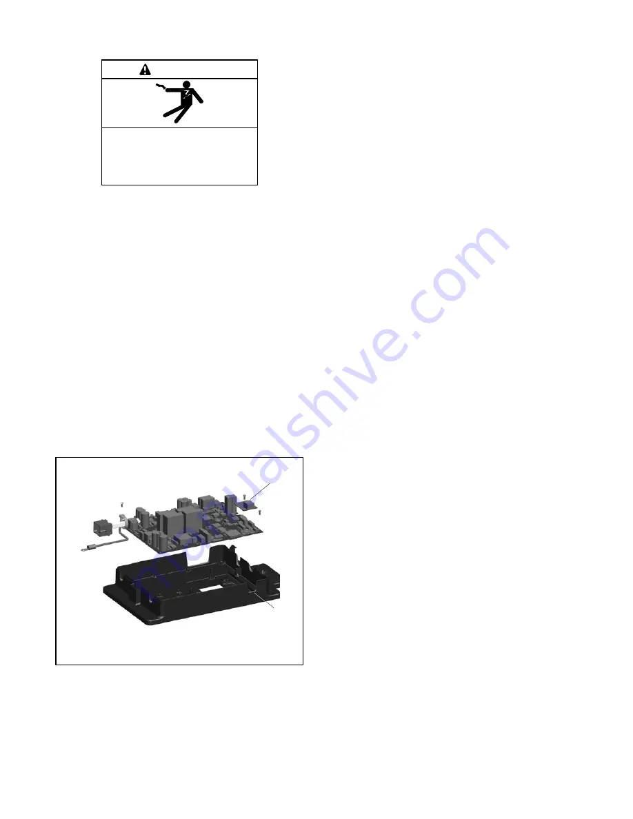
The Ethernet communication accessory board is
required for connection to the Ethernet. The Ethernet
communication board is standard on the MPAC 1500
controller. It is an optional accessory for the MPAC 1200
controller. The communication board connects to the
controller board as shown in Figure 4-5.
1. Ethernet communication board with RJ-45 connector
2. Access opening for Ethernet cable
GM85884
1
12
Figure 4-5
Ethernet Board (controller cover
removed for illustration only)
The Ethernet communication board allows the transfer
switch to be connected to a building’s Ethernet network
to communicate with personal computers connected to
the same subnet.
Note:
For an ethernet connection, obtain an IP address
and subnet mask number from the local system
administrator.
Ethernet Port.
The ethernet port is a standard RJ-45
jack. See Figure 4-5 for the location of the Ethernet port.
Use Category 5e or better cable to connect the controller
to the building’s network.
Use the controller’s Setup menus or a personal
computer connected to the controller’s USB port and
Kohler SiteTech software to set the communication
parameters. The Ethernet communication board may
have a default IP address assigned at the factory for test
purposes. See Figure 4-6.
Change the IP address to
an address owned by the user.
See the controller
operation manual for instructions to set the
communication parameters.
The transfer switch controller does not operate as a
Modbus-to-Ethernet converter for other devices in a
network. For multiple device networks connected to the
personal computer through the Ethernet, use a
Modbus-to-Ethernet converter for the other devices in
the network. See Figure 4-7 and instruction sheet
TT-1405, provided with the converter, for connection
instructions.
The controller can communicate with up to five (5)
simultaneous TCP/IP (ethernet) connections. These
five connections do not include the RS-485 serial port.
In the extreme case, five users may be communicating
with the controller via TCP/IP network connections and
another may be communicating through the serial port,
for a total of six (6) communication channels. As the
controller is asked to communicate with more and more
outside devices, the communication will slow down.
Содержание KCC
Страница 50: ...TP 6833 2 16 50 Section 4 Communication and Accessory Connections Notes...
Страница 54: ...TP 6833 2 16 54 Section 5 Functional Tests and Setup Notes...
Страница 57: ...TP 6833 2 16 57 Notes...
Страница 58: ...TP 6833 2 16 58 Notes...
Страница 59: ......


