9
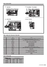
Rolling moment
Yawing moment
Pitching moment
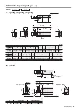
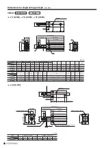
6 [0.236]
10 [0.394]
16 [0.630]
20 [0.787]
A
30 [1.181]
35 [1.378]
39 [1.535]
49 [1.929]
B
6 [0.236]
7 [0.276]
9.5 [0.374]
12 [0.472]
Handling Instructions and Precautions
Cylinder with guide - Allowable bending moment
Allowable loads
Fp,
Fy,
Fr calculation formula
Allowable bending moment
Moment from guide center location distance compensation
N · m [in · lbf]
6 [0.236]
10 [0.394]
16 [0.630]
20 [0.787]
Mp (Pitching)
0.39 [3.45]
0.39 [3.45]
0.51 [4.51]
1.02 [9.03]
Mr (Rolling)
0.58 [5.13]
0.58 [5.13]
1.02 [9.03]
2.08 [18.41]
My (Yawing)
0.47 [4.16]
0.47 [4.16]
0.51 [4.51]
1.02 [9.03]
Cylinder
bore mm [in.]
Cylinder
diameter mm [in.]
Allowable bending
moment
mm [in.]
Pitching (Mp)
Yawing (My)
Rolling (Mr)
Guide center location B
A
+
Stroke
For each moment center position, use the guide center location shown
in the figure as the reference.
Applications exceeding the allowable bending moment may damage the guide portion and deteriorate the accuracy, thereby affecting the operating life.
Symbol
Center of the guide
Lp
A
+
St
Fp
Mp
Fr
Mr
Lr
B
Center of the guide
Ly
A
+
St
Fy
My
Center of the guide
Fp =
Mp
×
1000
(N)
Lp
: Distance between the plate and the load (mm)
A
+
St
: Distance between the plate and the center of the guide (mm)
St
: Cylinder stroke (mm)
Lp
+
(A
+
St)
Fy =
My
×
1000
(N)
Ly
: Distance between the plate and the load (mm)
A
+
St
: Distance between the plate and the center of the guide (mm)
St
: Cylinder stroke (mm)
Ly
+
(A
+
St)
Fr =
Mr
×
1000
(N)
Lr : Distance between the plate and the load (mm)
B : Distance to the center of the guide (mm)
Lr
+
B
Содержание YMDA Series
Страница 34: ...33 MEMO ...


