32
Operation type
Non-rotating
double acting type
X
Y
Z
6 [0.236]
13 [0.512]
4.5 [0.177]
8 [0.315]
10 [0.394]
15 [0.591]
5.5 [0.217]
9 [0.354]
16 [0.63]
17 [0.669]
7.5 [0.295]
11 [0.433]
20 [0.787]
25 [0.984]
9.5 [0.374]
13 [0.512]
Non-contact type
6 [0.236]
9 [0.354]
1.5 [0.059]
4 [0.157]
10 [0.394]
11 [0.433]
2.5 [0.098]
5 [0.197]
16 [0.63]
13 [0.512]
4.5 [0.177]
7 [0.276]
20 [0.787]
21 [0.827]
6.5 [0.256]
9 [0.354]
Contact type
Operation type
Double acting type
Single acting push
type
Single acting pull
type
X
Y
Z
X
Y
Z
X
Y
Z
6 [0.236]
13 [0.512]
4.5 [0.177]
8 [0.315]
18 [0.709]
4.5 [0.177]
8 [0.315]
13 [0.512]
9.5 [0.374]
13 [0.512]
10 [0.394]
15 [0.591]
5.5 [0.217]
9 [0.354]
20 [0.787]
5.5 [0.217]
9 [0.354]
15 [0.591]
10.5 [0.413]
14 [0.551]
16 [0.630]
17 [0.669]
7.5 [0.295]
11 [0.433]
22 [0.866]
7.5 [0.295]
11 [0.433]
17 [0.669]
12.5 [0.492]
16 [0.630]
20 [0.787]
25 [0.984]
9.5 [0.374]
13 [0.512]
30 [1.181]
9.5 [0.374]
13 [0.512]
25 [0.984]
14.5 [0.571]
18 [0.709]
Solid state type
6 [0.236]
9 [0.354]
1.5 [0.059]
4 [0.157]
14 [0.551]
1.5 [0.059]
4 [0.157]
9 [0.354]
6.5 [0.256]
9 [0.354]
10 [0.394]
11 [0.433]
2.5 [0.098]
5 [0.197]
16 [0.630]
2.5 [0.098]
5 [0.197]
11 [0.433]
7.5 [0.295]
10 [0.394]
16 [0.63]
13 [0.512]
4.5 [0.177]
7 [0.276]
18 [0.709]
4.5 [0.177]
7 [0.276]
13 [0.512]
9.5 [0.374]
12 [0.472]
20 [0.787]
21 [0.827]
6.5 [0.256]
9 [0.354]
26 [1.024]
6.5 [0.256]
9 [0.354]
21 [0.827]
11.5 [0.453]
14 [0.551]
Reed switch type
Symbol
Symbol
Bore
Bore
Type
Type
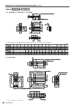
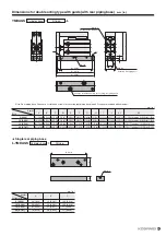
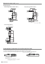
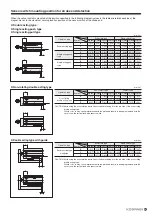
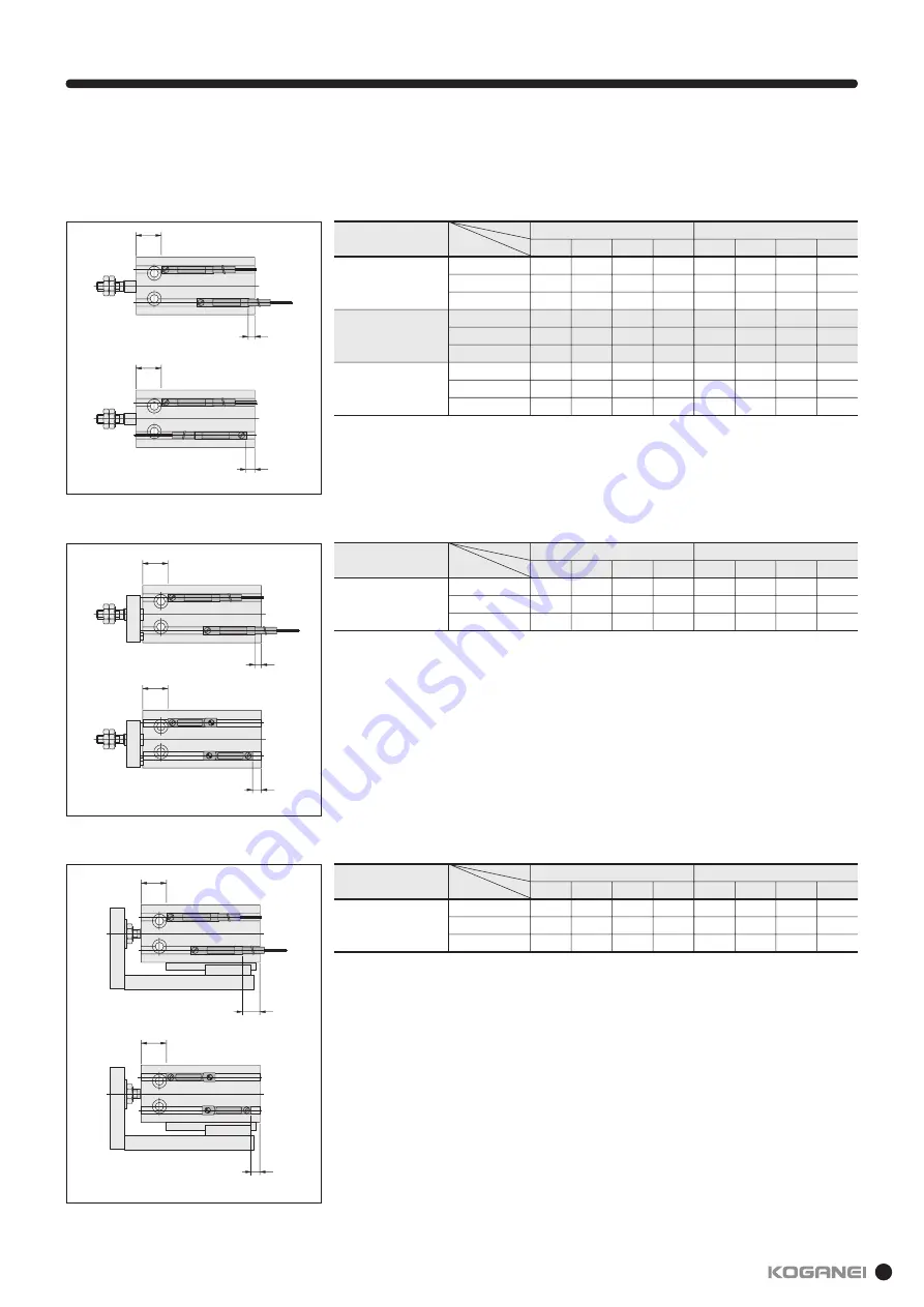
Sensor switch mounting position for stroke end detection
When the sensor switch is mounted at the position specified in the following diagram (values in the table are reference values), the
magnet moves to the maximum sensing location position of the sensor switch at the stroke end.
z
Double acting type
z
Single acting push type
z
Single acting pull type
X
Y
X
Y
X
Z
X
Z
X
Z
z
Non-rotating double acting type
z
Double acting type with guide
X
Y
mm [in.]
mm [in.]
Operation type
Double acting type
with guide
X
Y
Z
6 [0.236]
13 [0.512]
4.5 [0.177]
8 [0.315]
10 [0.394]
15 [0.591]
5.5 [0.217]
9 [0.354]
16 [0.630]
17 [0.669]
7.5 [0.295]
11 [0.433]
20 [0.787]
25 [0.984]
9.5 [0.374]
13 [0.512]
Solid state type
6 [0.236]
9 [0.354]
1.5 [0.059]
4 [0.157]
10 [0.394]
11 [0.433]
2.5 [0.098]
5 [0.197]
16 [0.630]
13 [0.512]
4.5 [0.177]
7 [0.276]
20 [0.787]
21 [0.827]
6.5 [0.256]
9 [0.354]
Reed switch type
mm [in.]
CAUTION: Avoid using the horizontal lead wire sensor switch inserting from the rod side of the non-rotating
double acting type.
Failure to do so may cause interference with the plate and results in damaging the lead wire. Be
sure to use the vertical lead wire sensor switch.
CAUTION: Avoid using the horizontal lead wire sensor switch inserting from the rod side of the non-rotating
double acting type.
Failure to do so may cause interference with the plate and results in damaging the lead wire. Be
sure to use the vertical lead wire sensor switch.
Symbol
Bore
Type
Содержание YMDA Series
Страница 34: ...33 MEMO ...

