background image

13

Product Wiring

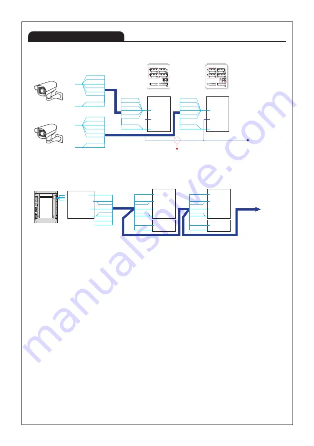
■ CAM1 - CCTV, CAM2 - 420system Connection (Ex-indoor monitor Connection)

※ Extension calling is available by using CAMERA1's audio line.

     Hence, when connecting CCTV with CAM1 you MUST use  

    CAMERA1's #3 CA1 AUDIO port to connect Ex-monitor so that

   it can perform extension calling.

※ Remark: Ex-monitor means extended monitors

CAM2 : KVS-A4P/A8P 

(For 420System)

Ex-Monitor

VCC
GND
AUDIO
VIDEO

Indoor monitor

Ex-Indoor monitor

CAM1 : CCTV

①CA1 VCC

②CA1 GND

③CA1 AUDIO

④CA1 VIDEO

①CA1 VCC

②CA1 GND

③CA1 AUDIO

④CA1 VIDEO

A

A

External Power Input

External Power Input

CAMERA 1

CAMERA 1

CCTV

CCTV

GND

VIDEO

ORANGE

W/BLUE

W/ORANGE

BLUE

W/BROWN
BROWN
W/GREEN
GREEN

GND

VIDEO

ORANGE

W/BLUE

W/ORANGE

BLUE

W/BROWN
BROWN
W/GREEN
GREEN

ORANGE

W/BLUE

W/ORANGE

BLUE

W/BROWN

BROWN

W/GREEN

GREEN

ORANGE

W/BLUE

W/ORANGE

BLUE

W/BROWN

BROWN

W/GREEN

GREEN

※ CAT5 wire configuration
※ UTP CAT5e : The resistance of 100 m of cable should be 10 ohms or less.    
※ More than 50 meters of distance may cause quality failure. Recommended wire specification as follow.
    - Upto 50m : TIV 0.65㎟ cable
    - Upto 100m : Over TIV 0.8㎟ cable
    - Upto 150m : TIV 0.8㎟ cable + RG-59 / U RG-59 / U (Coaxial cable) for Video signal
       (Connect core to Video & shield to GND)
※ Apart from product malfunction, installed environment may cause failure of video quality.
    Optimal distance from camera to monitor is about 50 meters.
※ If the video quality is poor during the call between the door camera and the device, 
    Please check ths set value of last device. (Set > Camera > Last device)

Ex-Monitor

①VCC(BLUE)

②GND(YELLOW)

③AUDIO(RED)

④VIDEO(WHITE)

ORANGE

W/Orange

W/Blue

Blue

W/Green

Green

A

W/Brown

No connection

No connection

Brown

①CA2 VCC

②CA2 GND

③CA2 AUDIO

④CA2 VIDEO

①DATA
②GND

B

E

ORANGE

W/Orange

W/Blue

Blue

W/Green

Green

W/Brown

Brown

CAMERA 2

INNER DATA

①CA2 VCC

②CA2 GND

③CA2 AUDIO

④CA2 VIDEO

①DATA
②GND

B

E

ORANGE

W/Orange

W/Blue

Blue

W/Green

Green

W/Brown

Brown

CAMERA 2

INNER DATA

Содержание KCV-T701SM

Страница 1: ...nient UI Full Capacitvive screen Compatible with 1080p FHD AHD CCTV TVI AHD CVI Auto still image capture Max 32 cuts Door Camera Connection up to 2 Door Cameras and 4 Monitors with Sub interphone KIP...

Страница 2: ...ause it may expose you to dangerous voltages or other risks Even if your product is water proof do not install it slanted place of water leakage which can a short circuit Fix the product on the wall s...

Страница 3: ...ity In such case immediately turn down the power switch and call to consult agency or store in which this product was purchased Keep away from any conditions where water splatters or falls Do not plac...

Страница 4: ...ack light or shadow on visitor s face may occur difficult recognition Avoid installing camera in places such as the following picture 1 Place illuminating sky as background 2 Place with white wall ref...

Страница 5: ...acket 4X25mm 4X8mm Monitor Model No KCV T701SM AC TYPE KCV T701SM DC TYPE Power Source 100 240V 50 60Hz DC 14V 2A Power Consumption 1 7W 20 On Stand by MAX 14W 20 Full load Operating Temperature 0 40...

Страница 6: ...A B 1 1 3 4 KC MC24 D1 KC MC24M KC S81M D1 KC S81M2 VCC GND Audio Video Door Non polarity COM NO NC Camera angle knob Only KC MC30M Wire clamp KC MC24 D1 KC MC24M KC Q81P D1 KC Q81P D1 KC MC30M 2M AH...

Страница 7: ...d furthest from the camera should be set to Last device and the rest other monitors except the one chosen as Last Device must be set as X KC S81M D1 KC S81M D1 KIP 32G KIP 32G KIP 32G KIP 32G Non Pola...

Страница 8: ...LITY OF VIDEO IMAGE KIP 32G BACKVIEW A CAMERA 1 CA1 VCC CA1 GND CA1 AUDIO CA1 VIDEO B CAMERA2 420 SYSTEM CA2 VCC CA2 GND CA2 AUDIO CA2 VIDEO C INTERPHONE INTER VCC INTER GND INTER AUDIO INTER SIGNAL D...

Страница 9: ...2 AUDIO CA2 VIDEO C INTERPHONE INTER VCC INTER GND INTER AUDIO INTER SIGNAL D DOOR 12V GND DOOR NO DOOR COM DOOR NC E INNER DATA DATA GND A 1 4 KC S81M D1 BACKVIEW A DEVICE1 BACKVIEW DEVICE2 BACKVIEW...

Страница 10: ...nection Terminal A CAMERA 1 CA1 VCC CA1 GND CA1 AUDIO CA1 VIDEO C INTERPHONE INTER VCC INTER GND INTER AUDIO INTER SIGNAL B CAMERA2 420 SYSTEM CA2 VCC CA2 GND CA2 AUDIO CA2 VIDEO D DOOR 12V GND DOOR N...

Страница 11: ...extended monitor It may not work if the wire length is more than 50 meters At this time reduce the wire resistance value by using four wires in a bundle of UTP cable Please select No or NC according...

Страница 12: ...ORANGE W Orange W Blue Blue W Green Green A W Brown No connection No connection Brown A B 1 1 3 4 CA1 VCC CA1 GND CA1 AUDIO CA1 VIDEO DATA GND A E ORANGE W Orange W Blue Blue W Green Green W Brown Br...

Страница 13: ...re configuration UTP CAT5e The resistance of 100 m of cable should be 10 ohms or less More than 50 meters of distance may cause quality failure Recommended wire specification as follow Upto 50m TIV 0...

Страница 14: ...correct wiring 8 8 8 8 8 8 X NC X NC X NC X NC 8 Correct wiring Incorrect wiring The monitor that is installed furthest from the camera should be set to Last device Refer to the page 20 for setting an...

Страница 15: ...tion as follow Upto 50m UTP CAT5e Upto 100m Coaxiable cabe RG 59 Connect core to Video shield to GND CA1 or 2 VCC CA1 or 2 GND CA1 or 2 AUDIO CA1 or 2 VIDEO IN OUT WIRING X Interphone connection Conne...

Страница 16: ...e How to Set Home Screen Setting Camera Last device Cam1 Cam2 O 3 CCTV Depending on the condition image at the door camera or CCTV may not be automatically detected In this case we recommend to use Ma...

Страница 17: ...n on the power switch placed at the top of its device and you will find booting progress and the home screen afterward in order When booting system will be automatically set as soon as the outdoor cam...

Страница 18: ...enu Icon for Monitoring Front Door CAM monitoring button Icon for Internal Call Internal call button Icon for Viewing to a Saved Capture Image Button for viewing the screen capture images Icon for Pre...

Страница 19: ...alling will be OFF Press door open button then you can open the door Talking time 180 secs Door opening time Default 2 seconds you can change at the Settings Calling From Outdoor Camera Touch drag By...

Страница 20: ...me control bar Brightness control bar Wide view Contrast control bar Saturation control bar Hue control bar Sharpness control bar Closing button Restore button You can adjust melody speaker volumes Yo...

Страница 21: ...n calling will be off When touching other buttons in the middle of the described function hereby you will hear BUZZ sound to alarm you When only one device is connected while calling the whole devices...

Страница 22: ...Calling wait time 30 secs Press guard button at home screen then guard calling will be on When calling the guard guard talk screen will be displayed Calling time 30 secs Display time gets counted from...

Страница 23: ...image view screen you can see stored images Press left or right arrow button then you can see other images Press delete button and deletion can be made right away Press home button at and the image li...

Страница 24: ...hoose O at the Last Device Extension talk is using CAM 1 s voice line so you MUST connect CAM 1 with all monitors in parallel Connect at CAM 2 terminal for the Lobby Guard configuration and choose eit...

Страница 25: ...camera image format NTSC PAL AHD 1080p 25 AHD 1080p 30 Manual NTSC In case of wrong selection in manual detection black colour background or abnormal image will be displayed from the LCD screen Manual...

Страница 26: ...afterimage on display due to continuously actived display We Kocom is not resoponsible for possible problem due to this mode and usage Auto capture When you select ON automatic screen capture availab...

Страница 27: ...27...

Страница 28: ...part 15 of the FCC Rules These limits are designed to provide reasonable protection against harmful interference in a residential installation This equipment generates uses and can radiate radio frequ...

Отзывы: