


14
15
Wiring diagram [cable requirement]
■ Upto 100M : CAT5 cable
■ Upto 50M : TIV 0.65㎟cable
■ Upto 100M : Over TIV 0.8㎟cable
■ Upto 150M : TIV 0.8㎟cable + RG-59 / U
RG-59 / U (Coaxial cable) for Video signal
(Connect core to Video & shield to GND)
※ Based on distance from a camera to the monitor
※ CAT5 wire configuration
※ In case of more than 50m of CAT5 cable length, the screen and voice quality can get lower.
But the sympthom is not a kind of fault. So less than 50m is recommended.
※ According to outside environment, you may view the images somewhat unclear.
However, they do not result from any defect or trouble of the product.
Orange
W / Orange
Green
W / Green
Blue
W / Blue
Brown
W / Brown
① VCC
double up
② GND
double up
③ Audio
double up
④ Video
double up
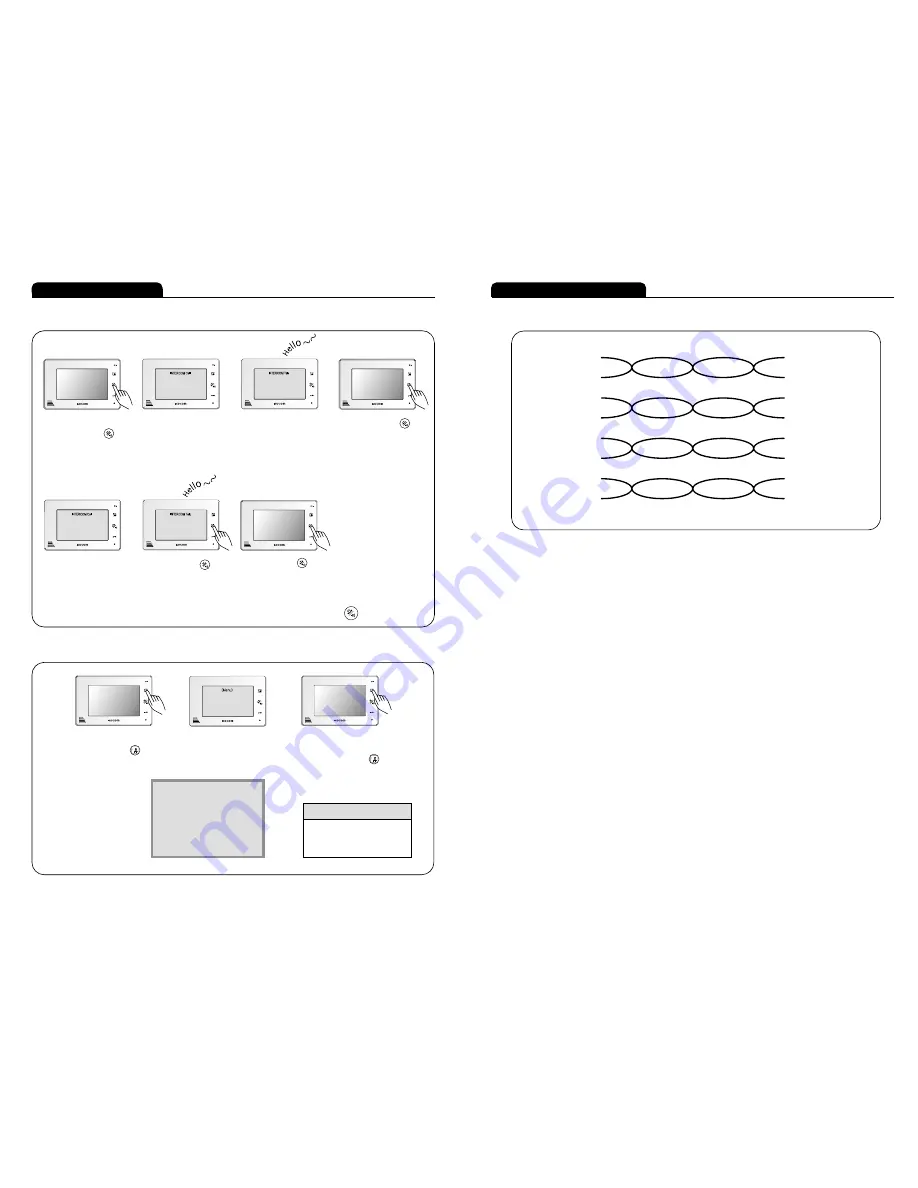
Instructions for operation
■ Extension call & communication
■ Special function selection
While the screen is off,
push the call button
for 1.5 second.
The screen turns on and
‘INTERCOM Call' is written
on OSD.
(INTERCOM Call Standby time
: 1 minute)
When connected to the sub-
monitor and sub-audiophone, the
main monitor will show 'INTERCOM
Talk' on OSD and the
communication turns on.
(INTERCOM Talk time : 3 minutes)
Push the call button
and stop INTERCOM Call.
�
�
�
When the screen off, push
the monitor button
for 4 seconds.
When the screen on, Menu
Mode OSD appears with the
cursor.
Menu Mode will disappear
automatically in 30 seconds.
Push the monitor button
for 4 seconds and Menu
Mode will turns off.
Menu for Special Function
�
�
□ Internal Call Receiving Mode
When receiving a call from Sub-
monitor and sub-audiophone, the
main monitor shows 'INTERCOM
Call' on OSD.
(INTERCOM Call Standby time
: 1 minute)
※ Caution : Push the call button for 1.5 second.
Push the call button
and INTERCOM Talk starts.
Push the call button again
and stop INTERCOM Talk.
�
�
<MENU>
��CAM1 : Bell 1 / 2 / 3 / 4 / 5
CAM2 : Bell 1 / 2 / 3 / 4 / 5
SUB : Bell 1 / 2 / 3 / 4 / 5
CAM1 View Time : 1MIN /
CAM2 View Time : 1MIN /
Cursor Guide
∙UP : Push the monitor button
∙Selection : Push the call button
∙Down : Push the door open button
□ Internal call sending mode


