


① Power switch
: Use by turning AC power ON / OFF.
② Monitor screen (LCD)
: Output of image sent from camera.
③ Speaker
④ Microphone
⑤ Monitor button
: Push this button to check around camera
when inside, and image is shown for 60 seconds.
(Voice intercepted between camera and monitor)
⑥ Extension button or Speak button
: Use this button to
start / stop speaking. On stanbying, the internal call is available
with pressing the button for 1.5 second. The call is available
with pressing the button when LCD screen is turned on.
⑦ Open door button
: Use this button to open front door with
connected door switch.
⑧ Power cord
⑨ Brightness adjustment volume
: Adjusting LCD screen
brightness to use.
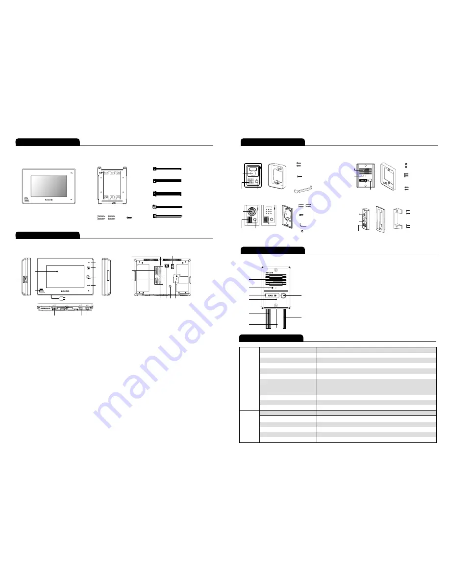
① White LED diffusion
: Has built-in white LED that works at night and flickers
when it gets dark around camera.
② Camera section
: Converts camera surroundings to visual signal and deliver to monitor.
③ Speaker
④ Microphone
⑤ Call button
: Push this button for output of call sound from monitor.
⑥ Monitor connection wire
: 4 wires by polarity
Blue : Vcc , Yellow : Ground , Red : Audio , White : Video
⑦ DC door opener connection wire
: DC 2 wires by non-polarity
⑧ FG : Frame ground
⑩ Call volume adjustment switch
: Adjusting call sound in 3 steps
[high, medium, low] to use. (In shipment : [medium])
* Cannot adjust call sound to
“none”
.
⑪ Speaking volume adjustment switch
: Adjust speaking volume
transmitted from camera to monitor in 3 steps [high, medium,
low]to use. (In shipment : [medium])
⑫ Camera 1 terminal
: Connects camera 1 with 4 wire polarity.
⑬ Camera 2 terminal
: Connects camera 2 with 4 wire polarity.
⑭ Sub audio phone terminal
: Connects sub audio phone with
6 wire polarity
⑮ Extension monitor terminal
: Connects extension monitor with
8 wire polarity
� Color adjustment volume
: Adjust color on LCD screen.
(In shipment, adjusted to standard color)
� Door2 - DC door switch terminal
: Connects (Camera2) DC door switch.
� Door1 -AC/DC door switch terminal
: Connects (Camera1) AC/DC door switch.
� Power input section
: Input AC power and fix power cord.
①
②
③
④
⑥
⑧
⑤
⑦
①
⑫
⑬
⑭
⑮
⑧
⑨
⑩
⑪
�
�
�
�
Name and Functions of each part
②
③
④
⑤
⑥
⑦
■ The front side
■ Camera (KC-MC24)
■ The back side
Components of product
Components of product
Name and Functions of each part
■ Monitor components
∙4 Pin cable for camera
∙8 Pin cable for monitor extension
∙2 Pin cable for monitor door opener (DC)
∙2 Pin cable for monitor door opener (AC/DC)
∙6 Pin cable for sub audio phone
(KDP-602G)
4×12mm 4ea
3×8mm 1ea
4P×2
6P
8P
2P
2P
■
Wire
■
A Wall hanger frame
■
Screw for fixing monitor
■
Monitor
Specifications
Model number
KCV-A374
6
7
Model number
KC-MC24
MONITOR
DOOR
CAMERA
Power Source
AC 100V-AC240V 50/60Hz
Power Consumption
Stand by 0.8W (±20%) , Max 13W (±20%)
Operating Temperature
0℃ ~ +40℃
Communication System
Handsfree type
LCD
7" Digital LCD (NTSC / PAL Auto switching)
Camera : 4 wire (Polarity)
Wiring
Sub audio phone : 6 wire (Polarity)
Extension monitor : 8 wire (Polarity)
Mount Type
Surface mount
Dimesion
222 (W) × 144 (H) × 33 (D) mm
Camera connection
KC-MC24, KC-C60, KC-MC20, KC-MC30, KC-MC31
Power Source
DC 12V ± 2V (Power from Monitor)
Power Consumption
Max 3W (±20%)
Operating Temperature
-10℃ ~ +50℃
Dimesion
96 (W) × 127 (H) × 32 (D) mm
Angle of Lens
1/4”
, 3.43mm/F.NO2.5, 96.1。
■ Door Camera components
Screws for fixing main
body on the wall
Screws for fixing camera
to main frame supporter
4×10mm
4×10mm
4×16mm
2.6×6mm
Screws for fixing main
body on the wall
Screws for fixing camera
to main frame supporter
4×25mm
4X8mm
“L”wench
Screw cap (KC-MC31)
[KC-C60]
Upward adjusting
supporter for lens angle
Lens
Speaker Call button
Lens
Speaker
Call button
Lens
Speaker Call button
Lens
Speaker
Call
button
[KC-MC24]
Finishing rubber
Main body
supporter
Main body
supporter
Main body
supporter
[KC-MC30]
[KC-MC31]
[KC-MC20]
Main body
supporter
or
Screw for fixing
camera main
body supporter
Screw for fixing
camera
3X5mm
2×8mm
Screw for fixing
camera
Screw for fixing
camera


