


2.2 Gas Ballast
All RA Series pumps are equipped with a gas ballast
valve. The gas ballast valve (Ref. 440) is located
between the inlet port and the exhaust box. RA0010 and
RA0016 pumps are equipped with a permanent gas bal-
last which cannot be shut off unless the sintered filter is
removed and the orifice plugged. Pumps RA0160 thru
RA1600 are equipped with an adjustable gas ballast
valve.
The adjustable gas ballast valve should normally be left
open. Its primary function is to prevent water vapor from
condensing in the pump. Condensation causes emulsi-
fication of the oil, loss of lubricity, and possible rotor
seizure.
2.3 Process Gas
The R5 series pumps are designed to pump air and are
not intended for use when water vapor is being pumped.
In some applications, when the quantity of the water
vapor is moderate, R5 pumps have been used with good
results. On these occasions, the pump is run until it is up
to operating temperature before it is allowed to pump the
process gas. The pump is also operated for a period of
time off process and on air (to clear it of process gas)
before it is shut down. This operating technique prevents
the vapor from condensing in the pump. Before attempt-
ing to pump a gas laden with water vapor, contact Busch
Engineering for advice.
2.4 Stopping Pump
To stop the pump, turn off the power. The pump has a
built-in, anti-suck-back valve (Ref. 251 thru 255) to pre-
vent the pump from rotating backwards when it is shut
off.
Install an automatic operated valve (such as a check
valve) in front of the pump, if more than one pump is
pumping on the same line or if there is a sufficient vol-
ume of vacuum in the system to cause the pump oil to be
drawn into the piping when that pump is shut down.
All R5 Series pumps are vented internally to atmospher-
ic pressure through venting holes that are next to the
exhaust valve assembly.
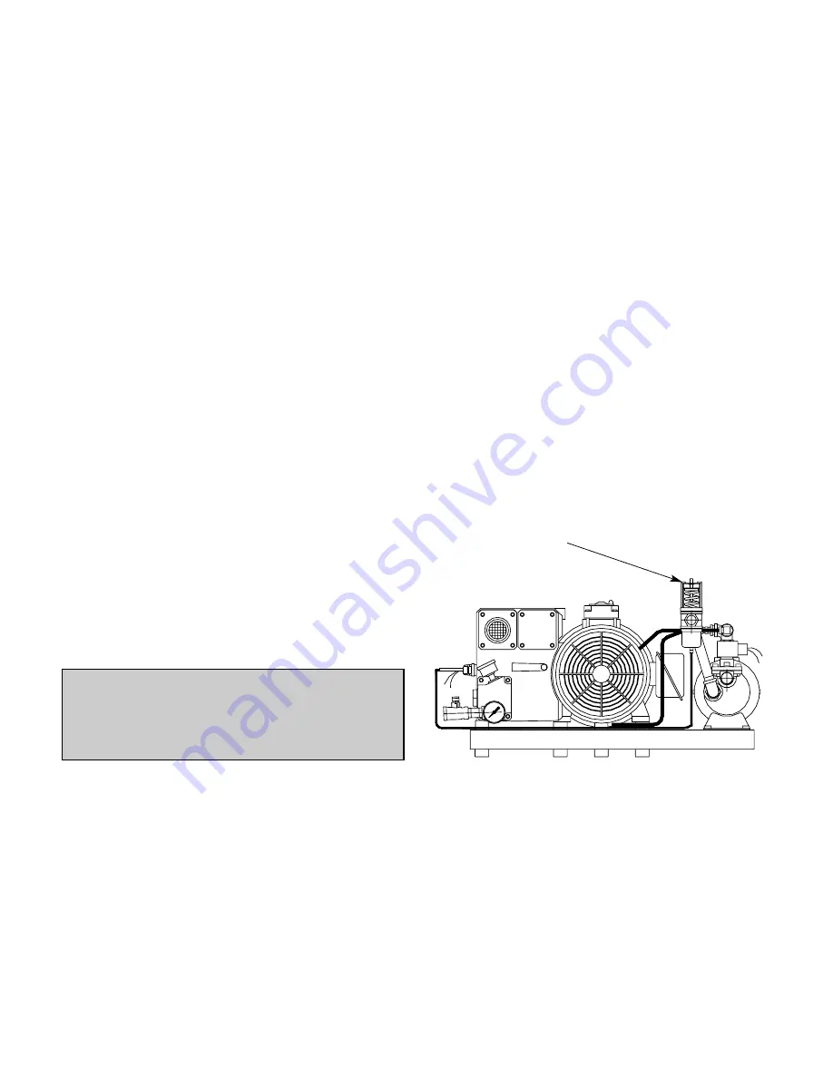
2.5 Water-Cooled Pumps (optional)
Water-cooled pumps are cooled by circulating the oil
through a shell-and-tube type heat exchanger. The cir-
culation of the pump oil through the shell is created by
vacuum in the pump, but the circulation of the cooling
water through the tubes is thermostatically controlled.
The flow rate of the cooling water is controlled by a ther-
mostatically activated valve (see Fig. 2) that senses,
through a capillary bulb mounted in the exhaust box, the
pump's oil temperature as it is discharged from the com-
pression chamber. The valve will open at its set point
and close at approximately 3°F to 5°F below the set
point. The valve set point is adjustable as follows:
(a) Rotate the valve adjustment screw counterclockwise
to cause the valve to open at a higher temperature. This
makes the pump run hotter.
(b) Rotate the valve adjustment screw clockwise to make
the valve open at a lower temperature. This makes the
pump run cooler.
The thermostatic valve can be manually opened by
inserting a screwdriver under each side of the spring
guide and prying the spring and guide upward away from
the valve body.
The water cooling option can be used to cool pumps
operating in high ambient temperatures, or it can be used
to maintain a pump at elevated temperatures to prevent
condensation inside the pump in wet applications.
Contact Busch Engineering in Virginia Beach for details.
2.6 Oxygen Service Pumps
Oxygen service pumps must be used in oxygen enriched
applications that are defined as any application which
has a process gas that is 25% or more oxygen. If this
pump is contaminated by organic compounds, do not
attempt to use it on oxygen service until it has been
decontaminated.
These pumps have been manufactured, solvent washed
(to remove organic contaminants) and assembled
Caution: Do not use the anti-suck-back valve as a
check or shut-off valve for your vacuum system. Do
not depend on the anti-suck-back valve to prevent
pump oil from migrating through the inlet into the
system when the pump is shut down.
Fig. 2 - Water-Cooled Pump
Thermostatic
Valve
5


