background image

7/12

» User Manual - Digital Tester K154433N50

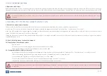
4. Checking of wear status of brake pads and disc

Note, this check is only possible for brakes having a ‘continuous‘ sensor (potentiometer) and therefore it is necessary to test if such a potentiometer is fitted:
 

Depending on accessibility it may be necessary to remove the wheel.


Disconnect the vehicle cable plugged into the potentiometer on the caliper.


Select the measuring cable depending on plug variant (screwed or clamped) and connect it with the tester.


Connect and fix the 3-pin plug to the potentiometer connector of the caliper.


Turn the rotary switch to position “End Wear Display black/white“.


 If the tester indicates a value < 0.2V or > 4.8V then a ‘continuous‘ sensor is not installed and the wear status of brake pads and disc cannot be determined by means of the 
tester. Carry out an optical check of the wear status - see the respective service manual. For detailed instructions on the necessary service steps - refer to section “Brake 
Identification and Service Manuals“.

The following steps therefore assume a ‘continuous‘ wear sensor is fitted.

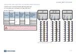
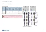
Turn the rotary switch of the test device to the respective vehicle and brake type (see tables in section 5).
Compare the indicated measured value with the value of the reference table (see section 6).
If the test device always indicates a value 0.00 V check the position of the rotary switch and the connection to the potentiometer connector.
Using the measured voltage you can find the wear status in the tables (see section 6).
If the value is < 2.75 Volt the green LED is illuminated. The wear status of brake pads and disc is OK.
If the value is ≥ 2.75 Volt the red LED is illuminated. The wear status of brake pads and disc must be checked with the wheels removed - refere to respective service manual.
A determination of the wear status (brake pads and disc) using the red or green LED requires the proper function of the potentiometer - see also section 3.


Re-adjust the tappets using the shear adapter until the tappet to caliper distance is the required value for “Minimum Disc + Pads dimension” – see table in section 7.


 Compare the indicated measured value with the value on the reference table (see section 6). If the tester always indicates a value 0.00 V the position of the rotary switch 
and the connection to the potentiometer should be checked. 


If the measured values correspond with the values in the tables within a range of ±0.25V the potentiometer function is correct.


Otherwise the caliper must be replaced.

CHECKING OF WEAR STATUS OF BRAKE PAD AND DISC

Содержание K154433N50

Страница 1: ...DIGITAL TESTER K154433N50 FOR DISC BRAKE WEAR POTENTIOMETER Reference No K066644 Doc No Y119119 EN Rev 001 July 2020 USER MANUAL...

Страница 2: ...en working under or around the vehicle and particularly when working in the engine compartment the engine should be shut off and the battery disconnected Where circumstances require that the engine be...

Страница 3: ...make certain that all components and the complete brake systems are leak free and restored to their proper operating condition Welding To avoid damage to electronic components when carrying out elect...

Страница 4: ...contrary to this specification may damage the device When fitting the battery ensure the correct polarity plus and minus Warranty claims will not be honoured if the device has been opened except the b...

Страница 5: ...c brakes and for the determination of the wear of the brake disc and brake pads 3 pin plug for threaded connection 3 pin plug for clamp connection Battery cover Display Red LED Wear indication Yellow...

Страница 6: ...l be necessary to measure over the disc using a vernier caliper or suitable fabricated device 3 1 Read the Safety Advice Section of this manual 3 2 Only if caliper is installed on vehicle Remove wheel...

Страница 7: ...e see tables in section 5 Compare the indicated measured value with the value of the reference table see section 6 If the test device always indicates a value 0 00 V check the position of the rotary s...

Страница 8: ...ania DAF Others DAF silver Voltage values increase between maximum gap and minimum gap from 1Volt to 3 5Volt linearly see section 6 1 Daimler Dana Evobus Hendrickson Hyundai Iveco Meritor SAF Scania S...

Страница 9: ...es for disc and brake pad gap measured voltages 6 1 For switch position cont Daimler Iveco Scania DAF Others Adjuster must only be turned using the shear adapter TABLES FOR DISC AND PAD GAP MEASURED V...

Страница 10: ...92 3 89 1 85 9 82 7 79 5 76 9 73 2 70 0 Y119119 EN REV 001 JULY 2020 6 2 For switch position cont MAN Adjuster must only be turned using the shear adapter Brake type Maximum disc and brake pad gap mm...

Страница 11: ...are valid under the condition that the switch position is selected according to the wear indicator used in the brake see section 5 7 Disc and brake pad gap voltage check setting dimensions DISC AND BR...

Страница 12: ...se Please check our website www knorr bremseCVS com for the latest update or contact your local Knorr Bremse representative The information does not purport to be all inclusive and no responsibility i...

Отзывы: