9/12
SB5...
SN5...
SL7...
SM7...
SB6... / SB7...
SN6... / SN7...
Volt
mm
%
Volt
mm
%
Volt
mm
%
1,00
1,25
1,50
1,75
2,00
2,25
2,50
2,75
3,00
3,25
3,50
0
10
20
30
40
50
60
70
80
90
100
96
93
90
87
84
81
78
75
72
69
66
105,0
101,5
97,5
94,0
90,0
86,5
83,0
79,0
75,5
71,5
68,0
110,0
106,5
102,5
99,0
95,0
91,5
88,0
84,0
80,5
76,5
73,0
0
10
20
30
40
50
60
70
80
90
100
0
10
20
30
40
50
60
70
80
90
100
1,00
1,25
1,50
1,75
2,00
2,25
2,50
2,75
3,00
3,25
3,50
1,00
1,25
1,50
1,75
2,00
2,25
2,50
2,75
3,00
3,25
3,50
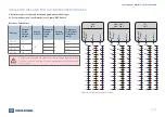
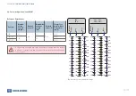
» User Manual - Digital Tester K154433N50
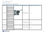
6. Reference tables for disc and brake pad gap & measured voltages
6.1. For switch position “cont. Daimler Iveco, Scania, DAF, Others“
*) Adjuster must only be turned using the shear adapter
TABLES FOR DISC AND PAD GAP & MEASURED VOLTAGES
Brake type
Maximum
disc and
brake pad
gap (mm)
Measured
voltage (V)
Minimum disc
and brake
pad gap
(mm)
Measured
voltage (V)
Change of gap
per full rotation
of the adjuster
*)
(mm / V)
SB5 / SN5
96
1,00
66
3,5
6 / 0,50
SB6 / SN6
105
68
6 / 0,41
SB7 / SN7
68
6 / 0,41
SL7 / SM7
110
73
6 / 0,41
Measur
ed
voltage
Measur
ed
voltage
Measur
ed
voltage
Gap
Gap
Gap
W
ear
W
ear
W
ear
All figures in this table are valid under the condition that the switch
position is selected according to the wear indicator used in the brake
(see section 5)
Reference Point Values


