KMD-5575
4
Installation and Operation Guide
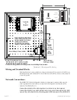
2"
Min.
2" Min.
Next
A
Next
B
(L)
(N)
Power
Limited
Not
Power
Limited
Power
Limited
Branch
Circuit
120 VAC
15 A, 60 Hz
Controller
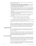
Provide 15 Amp Branch Circuit:
120 VAC, 60 Hz, 60°
C, Cu Wire 14 AWG
Panel Disconnect Provided by Installer
Power Limited and Non-Power
Limited wiring must be
perma-
nently separated by 2 inches
(minimum) and shall
be
accomplished by clamping,
routing, or equivalent means
Follow all local regulations and wiring codes when installing these products
Repeater
or
Class 2 Wiring = Power Limited
Class 1 Wiring =
Not Power Limited
Network Connections
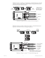
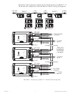
The KMD-5575 Network Repeater-Isolator is designed to operate between net
-
work segments. Each network is connected to the respective terminals on the
module. (See Illustration 1.)
Connect the shields of the cable together at each device on that segment.
Connect the shields to an earth ground only at one end of the segment. Do NOT
connect the cable shield to the circuit/segment GND terminal on the KMD-5575.
4.0"
3.0"
Repeater
KMD-5575
STATUS
2
1
EOL
A
B
GND
EOL
A
B
NETWORK-2
NETWORK-1
24 VAC
NETWORK-1 & 2
Wiring and Terminal Blocks
Terminal blocks are removable for wiring convenience. Wire sizes 14–22 AWG can
be clamped into each terminal. No more than two (16 AWG) wires can be joined at
a common point.
Illustration 2—Mounting and Wire Routing


